
-
 $1.25
$1.25 -
 $1.25
$1.25 -
 $1.25
$1.25 -
 $1.25
$1.25 -
 $1.25
$1.25 -
 $1.25
$1.25 -
 $1.25
$1.25 -
 $1.25
$1.25 -
 $1.25
$1.25 -
 $1.25
$1.25 -
 $1.25
$1.25 -
 $1.25
$1.25 -
 $1.25
$1.25 -
 $1.25
$1.25 -
 $1.25
$1.25 -
 $1.25
$1.25 -
 $1.75
$1.75 -
 $2.00
$2.00 -
 $1.00
$1.00 -
 $1.25
$1.25 -
 $2.40
$2.40 -
 $4,500.00
 -
 $1,000.00
 -
 $2.00
$2.00 -
 $1.20
$1.20 -
 $1.25
$1.25 -
 $1.25
$1.25 -
 $1.25
$1.25 -
 $1.25
$1.25 -
 $1.25
$1.25 -
 $1.25
$1.25 -
 $0.00
$0.00 -
 $0.00
$0.00 -
 $1.25
$1.25 -
 $1.25
$1.25 -
 $1.25
$1.25 -
 $0.00
$0.00 -
 $1.25
$1.25 -
 $1.25
$1.25 -
 $1.25
$1.25 -
 $1.25
$1.25 -
 $1.25
$1.25 -
 $1.25
$1.25 -
 $1.25
$1.25 -
 $1.25
$1.25 -
 $1.25
$1.25 -
 $1.25
$1.25 -
 $1.25
$1.25 -
 $1.25
$1.25 -
 $1.25
$1.25 -
 $1.25
$1.25 -
 $1.25
$1.25 -
 $1.25
$1.25 -
 $1.25
$1.25 -
 $1.25
$1.25 -
 $1.25
$1.25 -
 $1.25
$1.25 -
 $1.25
$1.25 -
 $1.25
$1.25 -
 $1.25
$1.25 -
 $1.25
$1.25 -
 $1.25
$1.25 -
 $1.25
$1.25 -
 $0.00
$0.00
No products
Product successfully added to your shopping cart
There are 64 items in your cart. There is 1 item in your cart.
Categories
-
Carbon Steel Pipes & Tubes
- ASTM A106 SA106 Pipe
- ASTM A53 SA53 Pipe
- ASTM A135 SA135 Pipe
- ASTM A139 SA139 Pipe
- ASTM A179 SA179 Tubes
- ASTM A210 SA210 Tubes
- ASTM A333 SA333 Pipe
- ASTM A334 SA334 Pipe
- ASTM A500 SA500 Pipe
- ASTM A501 SA501 Pipe
- ASTM A512 SA512 Tube
- ASTM A513 SA513 Tube
- ASTM A517 SA517 Tube
- ASTM A519 SA519 Tube
- ASTM A671 SA671 Pipe
- ASTM A672 SA672 Pipe
- ASTM A252 Steel piling pipe
- Carbon Steel Seamless Pipe
- Carbon Steel Pipe Japan
- Carbon Steel Pipes Europe
- Carbon Steel Pipe China
-
Stainless Steel Pipes & Tubes
- Stainless Steel Tube, Tubing & Pipe
- ASTM A271 ASME SA271 Pipes/ Tubes
- ASTM A312 ASME SA312 Pipes/ Tubes
- ASTM A358 ASME SA358 Pipes/ Tubes
- ASTM A376 ASME SA376 Pipes/ Tubes
- ASTM A409 ASME SA409 Pipes/ Tubes
- ASTM A430 ASME SA430 Pipes/ Tubes
- ASTM A632 ASME SA632 Pipes/ Tubes
- ASTM A778 ASME SA778 Pipes/ Tubes
- ASTM A813 ASME SA813 Pipes/ Tubes
- ASTM A814 ASME SA814 Pipes/ Tubes
- ASTM A826 ASME SA826 Pipes/ Tubes
- ASTM A851 ASME SA851 Pipes/ Tubes
- ASTM A213 ASME SA213 Pipes/ Tubes
- ASTM A249 ASME SA249 Pipes/ Tubes
- ASTM A268 ASME SA268 Pipes/ Tubes
- ASTM A269 ASME SA269 Pipes/ Tubes
- ASTM A270 ASME SA270 Pipes/ Tubes
- ASTM A511 ASME SA511 Pipes/ Tubes
- ASTM A688 ASME SA688 Pipes/ Tubes
-
Alloy Steel Pipes & Tubes
-
Alloy Steel Tubes
- ASTM A213 T1 Alloy Steel Tube
- ASTM A213 T2 Alloy Steel Tube
- ASTM A213 T5 Alloy Steel Tube
- ASTM A213 T5b Alloy Steel Tube
- ASTM A213 T5c Alloy Steel Tube
- ASTM A213 T9 Alloy Steel Tube
- ASTM A213 T11 Alloy Steel Tube manufacturer and suppliers
- ASTM A213 T12 Alloy Steel Tube
- ASTM A213 T17 Alloy Steel Tube
- ASTM A213 T21 Alloy Steel Tube
- ASTM A213 T22 Alloy Steel Tube
- ASTM A213 T23 Alloy Steel Tube
- ASTM A213 T24 Alloy Steel Tube
- ASTM A213 T36 Alloy Steel Tube
- ASTM A213 T91 Alloy Steel Tube
- ASTM A213 T92 Alloy Steel Tube
- ASTM A213 T122 Alloy Steel Tube
- ASTM A213 T911 Alloy Steel Tube
- ASTM A513 Grade 8620 Alloy Steel Tube
- ASTM A513 Grade 4130 Alloy Steel Tube
- ASTM A513 Grade 4118 Alloy Steel Tube
- ASTM A513 Grade 4140 Alloy Steel Tube
- ASTM A513 Grade 8630 Alloy Steel Tube
-
Alloy Steel Pipes
- ASTM A335 P1 Alloy Steel Pipe
- ASTM A335 P2 Alloy Steel Pipe
- ASTM A335 P5 Alloy Steel Pipe
- ASTM A335 P5b Alloy Steel Pipe
- ASTM A335 P5c Alloy Steel Pipe
- ASTM A335 P9 Alloy Steel Pipe
- ASTM A335 P11 Alloy Steel Pipe Manufacturer & Suppliers
- ASTM A335 P12 Alloy Steel Pipe
- ASTM A335 P15 Alloy Steel Pipe
- ASTM A335 P21 Alloy Steel Pipe
- ASTM A335 P22 Alloy Steel Pipe Manufacturer and suppliers
- ASTM A335 P23 Alloy Steel Pipe
- ASTM A335 P24 Alloy Steel Pipe
- ASTM A335 P36 Alloy Steel Pipe
- ASTM A335 P91 Alloy Steel Pipe
- ASTM A335 P92 Alloy Steel Pipe
- ASTM A335 P122 Alloy Steel Pipe
- ASTM A335 P911 Alloy Steel Pipe
- Alloy Steel Pipe & Tube Specification
-
Alloy Steel Tubes
- Special Steel Grades Pipes & Tubes
- API 5L Pipe
- Titanium Pipes & Tubes
- Welded/ ERW Pipes
- Mild Steel Pipes & Tubes
- Ductile Iron Spun Pipe & Ductile Iron Flanged Pipe Cast
- Capillary Tube| Capillary Tubing
- Boiler Tube
- Heat exchanger tubes
- Cupro Nickel Tube
- Aluminium Tube
- Corten Steel Pipes & Tubes
- EIL Approved Pipes
- IBR Pipe/ Tube & Non IBR Pipe/ Tube
- Black Pipes
- Galvanised Steel Pipes/ GI Tubes
- SS Coiled Tubing/ Tubes
- SS Electropolished Pipes/ Tubes
- SS Rectangular Pipes/ Tubes
- SS Square Pipes/ Tubes
- Full comparison of the DIN and EN standards for pipes/tubes
- Stainless Steel Pipe grades comparison


Surplus stock of Steel Pipes & Tubes:
Specialist in:
Offering best price on:
Widest inventory of:
SS,CS,Alloy Steel Pipe Prices
- » Steel Pipe/ Tube Price Iran
- » Steel Pipe/ Tube Price USA
- » Steel Pipe/ Tube Price India
- » Steel Pipe/ Tube Price China
- » Steel Pipe/ Tube Price Indonesia
- » Steel Pipe/ Tube Price UK
- » Steel Pipe/ Tube Price UAE
- » Steel Pipe/ Tube Price Malaysia
- » Steel Pipe/ Tube Price Singapore
- » Steel Pipe/ Tube Price South Korea
- » Steel Pipe/ Tube Price Saudi Arabia
- » Steel Pipe/ Tube Price Japan
- » Steel Pipe/ Tube Price Thailand
- » Steel Pipe/ Tube Price Bangladesh
- » Steel Pipe/ Tube Price Canada
- » Steel Pipe/ Tube Price Germany
- » Steel Pipe/ Tube Price Australia
- » Steel Pipe/ Tube Price Nigeria
- » Steel Pipe/ Tube Price Iraq
- » Steel Pipe/ Tube Price Turkey
- » Steel Pipe/ Tube Price Brazil
- » Steel Pipe/ Tube Price Vietnam
- » Steel Pipe/ Tube Price South Africa
- » Steel Pipe/ Tube Price Egypt
- » Steel Pipe/ Tube Price Bahrain
- » Steel Pipe/ Tube Price France
- » Steel Pipe/ Tube Price Mexico
- » Steel Pipe/ Tube Price Netherlands
- » Steel Pipe/ Tube Price Taiwan
- » Steel Pipe/ Tube Price Spain
- » Steel Pipe/ Tube Price Philippines
- » Steel Pipe/ Tube Price Pakistan
- » Steel Pipe/ Tube Price Kuwait
- » Steel Pipe/ Tube Price Norway
- » Steel Pipe/ Tube Price Oman
- » Steel Pipe/ Tube Price Qatar
- » Steel Pipe/ Tube Price Russia
- » Steel Pipe/ Tube Price Slovakia
- » Steel Pipe/ Tube Price Poland
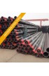
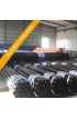
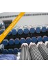
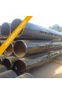
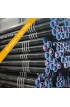
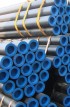
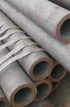
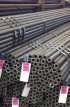
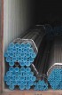
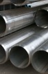
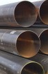
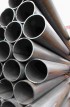
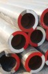
ASTM A135 / ASME SA135 / Pipe Steel Electric Fusion (ARC) Welded supplier & distributor in India


ASTM A 135-89a / ASME SA 135-89a
Pipe Steel Electric Fusion(ARC) Welded
This standard is issued under the fixed designation A 135; the number immediately following the designation indicates the year of original adoption or, in the case of revision, the year of last revision. A number in parentheses indicates the year of last reapproval. A superscript epsilon ( ε) indicates an editorial change since the last revision or reapproval. This specification has been approved for use by agencies of the Department of Defense. Consult the DoD Index of Specifications and Standards for specific year of issue which has been adopted by the Department of Defense.
1.Scope
1.1 This specification covers two grades of electric-resistance-welded steel pipe in NPS 2 TO NPS 30 inclusive, with nominal (average) wall thickness up to 0.500 in. ( 12.70 mm), inclusive, and in nominal sizes 3/4 to 5 in. (19 to 127 mm) inclusive with nominal (average) wall thickness 0.083 in. (2.11 mm) to 0.314 in. (3.40 mm), depending on size.Pipe having other dimensions 9Note 1) may be furnished provided such pipe complies with all other requirements of this specification.
The pipe in intended for conveying liquid, gas, or vapor; and only Grade A is adapted for flanging and bending (Note 2). The suitability of pipe for various purposes in somewhat dependent upon its dimensions, properties, and conditions of service, so that the purpose for which the pipe is intended should be stated in the order.
T he pipe may be furnished either nonexpanded or cold expanded, the amount of expansion shall not exceed
1.5? of the outside diameter pipe size.
NOTE 1? A comprehensive listing of standardized pipe dimensions is contained in ANSI B36.10.
NOTE 2? This provision is not intended to prohibit the cold bending of Grade B pipe.
1.2 The values stated in inch-pound units are to be regarded as the standard.
Chemical composition
| Grade | Mfg. process | Chemical Composition (%) | ||||
| C | Si | Mn | P | S | ||
| Gr A | E | 0.25Max | - | 0.95Max | 0.050Max | 0.060Max |
| Gr B | E | 0.30Max | - | 1.20Max | 0.050Max | 0.060Max |
Mechanical Properties
| Grade | Tenssile Test MPa or N/mm2 | Remarks (Similar to JIS) | possibility temperature |
|
| MIn. Yield Point | Tensile Strength | |||
| Gr A | 207 | 331Min | (STPG370) | |
| Gr B | 241 | 414Min | (STPG410) | |
Chemical Composition
The steel shall conform to the following requirements as to chemical composition: %, max
| Element | Grade A | Grade B |
| Carbon | 0.25 | 0.30 |
| Manganese | 0.95 | 1.20 |
| Phosphorus | 0.035 | 0.035 |
| Sulfur | 0.035 | 0.035 |
| NPS | Numbers of Samples Selected |
| Under 6 | 2 form each lot of 400 pipes or fraction thereof |
| 6 to 20, incl | 2 form each lot of 200 pipes or fraction thereof |
| Over 20 to 30, incl | 2 form each lot of 100 pipes or fraction thereof |
TABLE 1 Tensile Requirements
| - | Grade A | Grade B | ||
| Tensile strength, min, psi (MPa) Yield strength, min, psi(MPa) Elongation in 2 in. or 50 mm, min, % Basic minimum elongation for walls 5/16 in. (7.9 mm) and over in thickness, longitudinal strip tests,and for all samll sizes tested in full section For longitudinal strip tests, the width of the gage section shall be 1 1/2 in. (38.1 mm) and a deduction for each 1/32-in. (0.8-mm) decrease in wall thickness below 5/16 in. (7.9mm) from the basic minimum elongation of the following percentage points |
48 (331) | 60 (414) | ||
| 30 (207) | 35 (241) | |||
| 35 | 30 | |||
| 1.75A | 1.50A | |||
| A The following table gives the computed minimum values: | ||||
| Wall Thickness | Elongation in 2 in. (50 mm), min, % | |||
| Grade A | Grade B | |||
| 5/16 (0.312) (7.94 mm) | 35.00 | 30.00 | ||
| 9/32 (0.281) (7.14 mm) | 33.25 | 28.50 | ||
| 1/4 (0.250) (6.35 mm) | 31.50 | 27.00 | ||
| 7/32 (0.219) (5.56 mm) | 29.75 | 25.50 | ||
| 3/16 (0.188) (4.76 mm) | 28.00 | 24.00 | ||
| 5/32 (0.156) (3.97 mm) | 26.25 | 22.50 | ||
| 1/8 (0.125) (3.18 mm) | 24.50 | 21.00 | ||
| 3/32 (0.094) (2.38 mm) | 22.75 | 19.50 | ||
| 1/16 (0.062) (1.59 mm) | 21.00 | 18.00 | ||
Note-The above table gives the computed minimum eiongation values for each 1/32-in. (0.79-mm) decrease in wall thickness. Where the wall thickness lies between two vallues shown above. the minimum elongation value is determined by the following equation: |
| Grade | Equation |
| A | E = 56t + 17.50 |
| B | E = 48t + 15.00 |
where: E = elongation in 2 in. (50 mm), %, and t = actual thickness of spectimen, in. |
APPENDIX (Nonmandatory Information) X1.
ADDITIONAL DATA TABLE X1.1
Table of Minimum Wall Thickness on Inspection for Nominal (Average) Pipe Wall Thicknesses
Note 1-The following equation, upon which this table is based, may be applied to calcalate minimum wall thickness from nominal (average) wall thickness: tn X 0.875 = tm where tn=nominal (average) wall thickness, in., and tm=minimum wall thickness,in. The wall thickness is expressed to three decimal places, the fourth decimal place being carried forward or dropped, in accordance with Practive E 29. Note 2-This table covers some wall thicknesses associated with standard pipe sizes but is not meant to imply that these are the only thicknesses obtainable under this specification. |
| Nominal (Average) Thickness(tn)in. mm |
Minimum Thickness on inspection(tm)in. mm |
Nominal (Average) Thickness(tn)in. mm |
Minimum Thickness on inspection(tm)in. mm |
Nominal (Average) Thickness(tn)in. mm |
Minimum Thickness on inspection(tm)in. mm |
| 0.068 (1.73) | 0.060 (1.52) | 0.294 (7.47) | 0.257 (6.53) | 0.750 (19.05) | 0.656 (16.66) |
| 0.088 (2.24) | 0.077 (1.96) | 0.300 (7.62) | 0.262 (6.65) | 0.812 (20.62) | 0.710 (18.03) |
| 0.091 (2.31) | 0.080 (2.03) | 0.307 (7.80) | 0.269 (6.83) | 0.843 (21.41) | 0.738 (18.75) |
| 0.095 (2.41) | 0.083 (2.11) | 0.308 (7.82) | 0.270 (6.86) | 0.864 (21.95) | 0.756 (19.20) |
| 0.013 (2.87) | 0.099 (2.51) | 0.312 (7.92) | 0.273 (6.93) | 0.875 (22.23) | 0.766 (19.46) |
| 0.119 (3.02) | 0.104 (2.64) | 0.318 (8.08) | 0.278 (7.06) | 0.906 (23.01) | 0.793 (20.14) |
| 0.125 (3.18) | 0.109 (2.77) | 0.322 (8.18) | 0.282 (7.16) | 0.937 (23.80 | 0.820 (20.83) |
| 0.126 (3.20) | 0.110 (2.79) | 0.330 (8.38) | 0.289 (7.34) | 0.968 (24.59) | 0.847 (21.51) |
| 0.133 (3.38) | 0.116 (2.95) | 0.337 (8.56) | 0.295 (7.49) | 1.000 (25.40) | 0.875 (22.23) |
| 0.140 (3.56) | 0.122 (3.10) | 0.343 (8.71) | 0.300 (7.62) | 1.031 (26.19) | 0.902 (22.91) |
| 0.145 (3.68) | 0.127 (3.23) | 0.344 (8.74) | 0.301 (7.65) | 1.062 (26.97) | 0.929 (23.60) |
| 0.147 (3.73) | 0.129 (3.28) | 0.358 (9.09) | 0.313 (7.95) | 1.093 (27.76) | 0.956 (24.28) |
| 0.154 (3.91) | 0.135 (3.43) | 0.365 (9.27) | 0.319 (8.10) | 1.125 (28.58) | 0.984 (24.99) |
| 0.156 (3.96) | 0.136 (3.45) | 0.375 (9.53) | 0.328 (8.33) | 1.156 (29.36) | 1.012 (25.70) |
| 0.179 (4.55) | 0.157 (3.99) | 0.382 (9.70) | 0.334 (8.48) | 1.218 (30.94) | 1.066 (27.08) |
| 0.187 (4.75) | 0.164 (4.14) | 0.400 (10.16) | 0.350 (8.89) | 1.250 (31.75) | 1.094 (27.79) |
| 0.188 (4.78) | 0.164 (4.14) | 0.406 (10.31) | 0.355 (9.02) | 1.281 (32.54) | 1.121 (28.47) |
| 0.191 (4.85) | 0.167 (4.24) | 0.432 (10.97) | 0.378 (9.60) | 1.312 (33.33) | 1.148 (29.16) |
| 0.200 (5.08) | 0.175 (4.45) | 0.436 (11.07) | 0.382 (9.70) | 1.343 (34.11) | 1.175 (29.85) |
| 0.203 (5.16) | 0.178 (4.52) | 0.437 (11.10) | 0.382 (9.70) | 1.375 (34.93) | 1.203 (30.56) |
| 0.216 (5.49) | 0.189 (4.80) | 0.438 (11.13) | 0.383 (9.73) | 1.406 (35.71) | 1.230 (31.24) |
| 0.218 (5.54) | 0.191 (4.85) | 0.500 (12.70) | 0.438 (11.13) | 1.437 (36.53) | 1.258 (31.95) |
| 0.219 (5.56) | 0.192 (4.88) | 0.531 (13.49) | 0.465 (11.81) | 1.500 (38.10) | 1.312 (33.33) |
| 0.226 (5.74) | 0.198 (5.03) | 0.552 (14.02) | 0.483 (12.27) | 1.531 (38.89) | 1.340 (30.04) |
| 0.237 (6.02) | 0.207 (5.26) | 0.562 (14.27) | 0.492 (12.50) | 1.562 (39.68) | 1.367 (34.72) |
| 0.250 (6.35) | 0.219 (5.56) | 0.593 (15.06) | 0.519 (13.18) | 1.593 (40.46) | 1.394 (35.41) |
| 0.258 (6.55) | 0.226 (5.74) | 0.600 (15.24) | 0.525 (13.34) | 1.750 (44.45) | 1.531 (38.89) |
| 0.276 (7.01) | 0.242 (6.15) | 0.625 (15.88) | 0.547 (13.89) | 1.781 (45.24) | 1.558 (39.57) |
| 0.277 (7.04) | 0.242 (6.15) | 0.656 (16.66) | 0.574 (14.58) | 1.812 (46.03) | 1.586 (40.28) |
| 0.279 (7.09) | 0.244 (6.20) | 0.674 (17.12) | 0.590 (14.99) | 1.968 (49.99) | 1.722 (43.74) |
| 0.280 (7.11) | 0.245 (6.22) | 0.687 (17.45) | 0.601 (15.27) | 2.062 (52.38) | 1.804 (45.82) |
| 0.281 (7.14) | 0.246 (6.25) | 0.719 (18.24) | 0.629 (15.98) | 2.343 (59.51) | 2.050 (52.07) |
TABLE X 1.2 Dimensions Nominal Weights and Test Pressures for Light Wall Steel Pipe
| NPS | Outside Diameter. in. |
Schedule 10 | Test Pressure, psi (MPa)A | ||
| Nominal Wall ThicknessA in. (mm) |
Weight, Ib/ft (kg/cm) | Grade A | Grade B | ||
| ¾ | 1.050 | 0.083 (2.11) | 0.86 (1.28) | 2500 (17.24) | 2500 (17.24) |
| 1 | 1.315 | 0.109 (2.77) | 1.40 (2.09) | 2500 (17.24) | 2500 (17.24) |
| 1¼ | 1.660 | 0.109 (2.77) | 1.81 (2.70) | 2400 (16.55) | 2500 (17.24) |
| 1½ | 1.900 | 0.109 (2.77) | 2.08 (3.10) | 2100 (14.48) | 2400 (16.55) |
| 2 | 2.375 | 0.109 (2.77) | 2.64 (3.93) | 1700 (11.72) | 1900 (13.10) |
| 2½ | 2.875 | 0.120 (3.05) | 3.53 (5.26) | 1500 (10.34) | 1700 (11.72) |
| 3 | 3.500 | 0.120 (3.05) | 4.33 (6.45) | 1200 (8.27) | 1400 (9.65) |
| 3½ | 4.000 | 0.120 (3.05) | 4.97 (7.41) | 1000 (6.89) | 1200 (8.27) |
| 4 | 4.500 | 0.120 (3.05) | 5.61 (8.36) | 900 (6.21) | 1100 (7.58) |
| 5 | 5.563 | 0.134 (3.40) | 7.77 (11.58) | 850 (5.86) | 1000 (6.89) |
A The test pressures are calculated by the following equation (but shall not exceed 2500 psi or 17.24 MPa): P =2St/D where: P = pressure, psi (MPa) S = fiber stress, 60 % of the specified minimum yield point, t = specified thickness of wall, in. (mm), andD = specified outside diameter, in. (mm). |
JIS Number and Corrensponding Foreign Standards
| JIS | ASTM | BS | DIN | NF | ISO | Index Number | ||||||||||||
| Standard Number | Grade | Type | Standard Number | Grade | Type | Standard Number | Grade | Type | Standard Number | Grade | Type | Standard Number | Grade | Type | Standard Number | Grade | Type | |
| G3454 | STPG370 (STPG38) | C | A135 | Gr A | C | 3601 | ERW360 | C | 1626 | St37.0 | C | A49-112 | TS27b | C | 559 | TS4 | C | C002 |
| A587 | - | C | " | S360 | C | 1629 | St37.0 | C | A49-141 | TS37a | C | 2604/2 | TS4 | C | ||||
| 17172 | StE210.7 | C | A49-142 | TS37a | C | 2604/3 | TW4 | C | ||||||||||
| " | TS37b | C | ||||||||||||||||
| A49-150 | TSE235 | C | ||||||||||||||||
| A49-212 | TS37c | C | ||||||||||||||||
| A49-242 | TS37c | C | ||||||||||||||||
| A49-250 | TAE24a | C | ||||||||||||||||
| A49-400 | TSE220 | C | ||||||||||||||||
| STPG410 (STPG42) | C | A135 | GrB | C | 3601 | ERW410 | C | 1626 | St44.0 | C | A49-112 | TS42b | C | 559 | TS9 | C | ||
| A524 | - | C | " | S410 | C | A49-141 | TS42b | C | 2604/2 | TW9 | C | |||||||
| A49-212 | TS42c | C | 2604/3 | TW9 | C | |||||||||||||
| A49-242 | TS42c | C | 3183 | E24-1 | C | |||||||||||||
| A49-250 | TSE26b | C | "; | E24-2 | ||||||||||||||
| A49-400 | TSE250 | C | ||||||||||||||||