
-
 $1.25
$1.25 -
 $1.25
$1.25 -
 $1.25
$1.25 -
 $1.25
$1.25 -
 $1.25
$1.25 -
 $1.25
$1.25 -
 $1.25
$1.25 -
 $1.25
$1.25 -
 $1.25
$1.25 -
 $1.25
$1.25 -
 $1.25
$1.25 -
 $1.25
$1.25 -
 $1.25
$1.25 -
 $1.25
$1.25 -
 $1.25
$1.25 -
 $1.25
$1.25 -
 $1.75
$1.75 -
 $2.00
$2.00 -
 $1.00
$1.00 -
 $1.25
$1.25 -
 $2.40
$2.40 -
 $4,500.00
 -
 $1,000.00
 -
 $2.00
$2.00 -
 $1.20
$1.20 -
 $1.25
$1.25 -
 $1.25
$1.25 -
 $1.25
$1.25 -
 $1.25
$1.25 -
 $1.25
$1.25 -
 $1.25
$1.25 -
 $0.00
$0.00 -
 $0.00
$0.00 -
 $1.25
$1.25 -
 $1.25
$1.25 -
 $1.25
$1.25 -
 $0.00
$0.00 -
 $1.25
$1.25 -
 $1.25
$1.25 -
 $1.25
$1.25 -
 $1.25
$1.25 -
 $1.25
$1.25 -
 $1.25
$1.25 -
 $1.25
$1.25 -
 $1.25
$1.25 -
 $1.25
$1.25 -
 $1.25
$1.25 -
 $1.25
$1.25 -
 $1.25
$1.25 -
 $1.25
$1.25 -
 $1.25
$1.25 -
 $1.25
$1.25 -
 $1.25
$1.25 -
 $1.25
$1.25 -
 $1.25
$1.25 -
 $1.25
$1.25 -
 $1.25
$1.25 -
 $1.25
$1.25 -
 $1.25
$1.25 -
 $1.25
$1.25 -
 $1.25
$1.25 -
 $1.25
$1.25 -
 $1.25
$1.25 -
 $0.00
$0.00
No products
Product successfully added to your shopping cart
There are 64 items in your cart. There is 1 item in your cart.
Categories
-
Carbon Steel Pipes & Tubes
- ASTM A106 SA106 Pipe
- ASTM A53 SA53 Pipe
- ASTM A135 SA135 Pipe
- ASTM A139 SA139 Pipe
- ASTM A179 SA179 Tubes
- ASTM A210 SA210 Tubes
- ASTM A333 SA333 Pipe
- ASTM A334 SA334 Pipe
- ASTM A500 SA500 Pipe
- ASTM A501 SA501 Pipe
- ASTM A512 SA512 Tube
- ASTM A513 SA513 Tube
- ASTM A517 SA517 Tube
- ASTM A519 SA519 Tube
- ASTM A671 SA671 Pipe
- ASTM A672 SA672 Pipe
- ASTM A252 Steel piling pipe
- Carbon Steel Seamless Pipe
- Carbon Steel Pipe Japan
- Carbon Steel Pipes Europe
- Carbon Steel Pipe China
-
Stainless Steel Pipes & Tubes
- Stainless Steel Tube, Tubing & Pipe
- ASTM A271 ASME SA271 Pipes/ Tubes
- ASTM A312 ASME SA312 Pipes/ Tubes
- ASTM A358 ASME SA358 Pipes/ Tubes
- ASTM A376 ASME SA376 Pipes/ Tubes
- ASTM A409 ASME SA409 Pipes/ Tubes
- ASTM A430 ASME SA430 Pipes/ Tubes
- ASTM A632 ASME SA632 Pipes/ Tubes
- ASTM A778 ASME SA778 Pipes/ Tubes
- ASTM A813 ASME SA813 Pipes/ Tubes
- ASTM A814 ASME SA814 Pipes/ Tubes
- ASTM A826 ASME SA826 Pipes/ Tubes
- ASTM A851 ASME SA851 Pipes/ Tubes
- ASTM A213 ASME SA213 Pipes/ Tubes
- ASTM A249 ASME SA249 Pipes/ Tubes
- ASTM A268 ASME SA268 Pipes/ Tubes
- ASTM A269 ASME SA269 Pipes/ Tubes
- ASTM A270 ASME SA270 Pipes/ Tubes
- ASTM A511 ASME SA511 Pipes/ Tubes
- ASTM A688 ASME SA688 Pipes/ Tubes
-
Alloy Steel Pipes & Tubes
-
Alloy Steel Tubes
- ASTM A213 T1 Alloy Steel Tube
- ASTM A213 T2 Alloy Steel Tube
- ASTM A213 T5 Alloy Steel Tube
- ASTM A213 T5b Alloy Steel Tube
- ASTM A213 T5c Alloy Steel Tube
- ASTM A213 T9 Alloy Steel Tube
- ASTM A213 T11 Alloy Steel Tube manufacturer and suppliers
- ASTM A213 T12 Alloy Steel Tube
- ASTM A213 T17 Alloy Steel Tube
- ASTM A213 T21 Alloy Steel Tube
- ASTM A213 T22 Alloy Steel Tube
- ASTM A213 T23 Alloy Steel Tube
- ASTM A213 T24 Alloy Steel Tube
- ASTM A213 T36 Alloy Steel Tube
- ASTM A213 T91 Alloy Steel Tube
- ASTM A213 T92 Alloy Steel Tube
- ASTM A213 T122 Alloy Steel Tube
- ASTM A213 T911 Alloy Steel Tube
- ASTM A513 Grade 8620 Alloy Steel Tube
- ASTM A513 Grade 4130 Alloy Steel Tube
- ASTM A513 Grade 4118 Alloy Steel Tube
- ASTM A513 Grade 4140 Alloy Steel Tube
- ASTM A513 Grade 8630 Alloy Steel Tube
-
Alloy Steel Pipes
- ASTM A335 P1 Alloy Steel Pipe
- ASTM A335 P2 Alloy Steel Pipe
- ASTM A335 P5 Alloy Steel Pipe
- ASTM A335 P5b Alloy Steel Pipe
- ASTM A335 P5c Alloy Steel Pipe
- ASTM A335 P9 Alloy Steel Pipe
- ASTM A335 P11 Alloy Steel Pipe Manufacturer & Suppliers
- ASTM A335 P12 Alloy Steel Pipe
- ASTM A335 P15 Alloy Steel Pipe
- ASTM A335 P21 Alloy Steel Pipe
- ASTM A335 P22 Alloy Steel Pipe Manufacturer and suppliers
- ASTM A335 P23 Alloy Steel Pipe
- ASTM A335 P24 Alloy Steel Pipe
- ASTM A335 P36 Alloy Steel Pipe
- ASTM A335 P91 Alloy Steel Pipe
- ASTM A335 P92 Alloy Steel Pipe
- ASTM A335 P122 Alloy Steel Pipe
- ASTM A335 P911 Alloy Steel Pipe
- Alloy Steel Pipe & Tube Specification
-
Alloy Steel Tubes
- Special Steel Grades Pipes & Tubes
- API 5L Pipe
- Titanium Pipes & Tubes
- Welded/ ERW Pipes
- Mild Steel Pipes & Tubes
- Ductile Iron Spun Pipe & Ductile Iron Flanged Pipe Cast
- Capillary Tube| Capillary Tubing
- Boiler Tube
- Heat exchanger tubes
- Cupro Nickel Tube
- Aluminium Tube
- Corten Steel Pipes & Tubes
- EIL Approved Pipes
- IBR Pipe/ Tube & Non IBR Pipe/ Tube
- Black Pipes
- Galvanised Steel Pipes/ GI Tubes
- SS Coiled Tubing/ Tubes
- SS Electropolished Pipes/ Tubes
- SS Rectangular Pipes/ Tubes
- SS Square Pipes/ Tubes
- Full comparison of the DIN and EN standards for pipes/tubes
- Stainless Steel Pipe grades comparison


Surplus stock of Steel Pipes & Tubes:
Specialist in:
Offering best price on:
Widest inventory of:
SS,CS,Alloy Steel Pipe Prices
- » Steel Pipe/ Tube Price Iran
- » Steel Pipe/ Tube Price USA
- » Steel Pipe/ Tube Price India
- » Steel Pipe/ Tube Price China
- » Steel Pipe/ Tube Price Indonesia
- » Steel Pipe/ Tube Price UK
- » Steel Pipe/ Tube Price UAE
- » Steel Pipe/ Tube Price Malaysia
- » Steel Pipe/ Tube Price Singapore
- » Steel Pipe/ Tube Price South Korea
- » Steel Pipe/ Tube Price Saudi Arabia
- » Steel Pipe/ Tube Price Japan
- » Steel Pipe/ Tube Price Thailand
- » Steel Pipe/ Tube Price Bangladesh
- » Steel Pipe/ Tube Price Canada
- » Steel Pipe/ Tube Price Germany
- » Steel Pipe/ Tube Price Australia
- » Steel Pipe/ Tube Price Nigeria
- » Steel Pipe/ Tube Price Iraq
- » Steel Pipe/ Tube Price Turkey
- » Steel Pipe/ Tube Price Brazil
- » Steel Pipe/ Tube Price Vietnam
- » Steel Pipe/ Tube Price South Africa
- » Steel Pipe/ Tube Price Egypt
- » Steel Pipe/ Tube Price Bahrain
- » Steel Pipe/ Tube Price France
- » Steel Pipe/ Tube Price Mexico
- » Steel Pipe/ Tube Price Netherlands
- » Steel Pipe/ Tube Price Taiwan
- » Steel Pipe/ Tube Price Spain
- » Steel Pipe/ Tube Price Philippines
- » Steel Pipe/ Tube Price Pakistan
- » Steel Pipe/ Tube Price Kuwait
- » Steel Pipe/ Tube Price Norway
- » Steel Pipe/ Tube Price Oman
- » Steel Pipe/ Tube Price Qatar
- » Steel Pipe/ Tube Price Russia
- » Steel Pipe/ Tube Price Slovakia
- » Steel Pipe/ Tube Price Poland
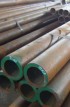
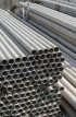
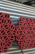
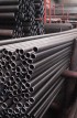
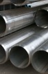
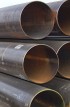
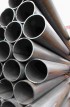
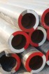
ASTM A513 / ASME SA513 / Electric Resistance Welded Carbon and Alloy Steel Mechanical Tubing supplier & distributor in India


ASTM A513-88 / ASME SA 513
ELECTRIC RESISTANCE WELDED CARBON
AND ALLOY STEEL MECHANICALTUBING
1. SCOPE
1.1 This specification covers electric-resistance-welded carbon and alloy steel tubing for use as mechanical tubing.
1.2 This specification covers mechanical tubing made from hot- or cld-rolled steel.
1.3 This specification covers round, square, rectangular, and special shape tubing.
| Type | Size Range(Round Tubing) |
| Electric-Resistance-Welded Tubing from Hot-Rolled Steel | outside diameter from 3/4 to 15 in.(19.0 to 38.1mm) |
| wall from 0.065 to 0.650 in.(1.65 to 16.50mm) | |
| Electric-Resistance-Welded Tubing from cold-Rolled Steel | outside diameter form 3/8 to 8 in.(9.52 to 203.2mm) |
| wall from 0.028 to 0.134 in.(0.71 to 3.40mm) |
1.4 Optional supplementary requirements are provided and when desired, shall be so stated in inch-pound units
are to be refarded as the standard. 1.5 The values stated in inch-pund units are to be regarded as the standard.
| Grade | Remaks (Similar to JIS) |
| MT 1010 | (STKM11) |
| MT 1015 | (STKM12) |
| MTX1015 | - |
| MT 1020 | (STKM13) |
| MTX1020 | - |
| 1008 | - |
| 1010 | - |
| MTX1015 | - |
| 1016 | - |
| 1017 | - |
| 1018 | - |
| 1019 | - |
| 1020 | - |
| 1021 | - |
| 1022 | - |
| 1023 | - |
| 1024 | - |
| 1025 | - |
| 1026 | (STKM14) |
| 1027 | - |
| 1030 | (STKM15) |
| 1033 | - |
| 1035 | - |
| 1040 | - |
| 1050 | - |
| 1060 | - |
| 1340 | - |
| 1524 | - |
| 4778 | - |
| 4130 | - |
| 4140 | - |
| 5130 | - |
| 8620 | - |
| 8630 | - |
In such cases for Types 1 and 2 (A.W.H.R. and A.W.C.R.) the ovality may be 50% greater than the outside
tolerances but the mean outside diameter shall be within the specified tolerance.
For Types 3.4.5. and 6 (S.D.H.R., S.D.C.R., M.D., and S.S.I.D) the additional ovality shall be as follows
but the mean outside diameter shall be within the specified tolerances ;
| Outside Diameter in (mm) | Additional Ovality Tolerance, in. (mm) |
| Up to 2 (50.8). incl | 0.010 (0.25) |
| Over 2 to 3 (50.8 to 76.2). incl | 0.015 (0.38) |
| Over 3 to 4 (76.2 to 101.6) incl | 0.020 (0.51) |
| Over 4 to 5 (101.6 to 127.0) incl | 0.025 (0.64) |
| Over 5 to 6 (127.0 to 152.4) incl | 0.030 (0.76) |
| Over 6 to 7 (152.4 to 177.8) incl | 0.035 (0.89) |
| Over 7 to 8 (177.8 to 203.2) incl | 0.040 (1.02) |
| Over 8 to 9 (203.2 to 228.6) incl | 0.045 (1.14) |
| Over 9 to 10 (228.6 to 254.0) incl | 0.050 (1.27) |
| Over 10 to 11 (254.0 to 279.4) incl | 0.055 (1.40) |
| Over 11 to 12 (279.4 to 304.8) incl | 0.060 (1.52) |
| Over 12 to 13 (304.8 to 317.5) incl | 0.065 (1.65) |
condition The types and conditions of tubing covered by this specification are:
| Type Number | Code Letters | Description |
| 1 | A.W.H.R | "as-welded" from hot-rolled steel |
| 2 | A.W.C.R | "as-welded" from cold-rolled steel |
| 3 | S.D.H.R | "sink-drawn" hot-rolled steel |
| 4 | S.D.C.R | "sink-drawn" cold-rolled steel |
| 5 | M.D | mandrel drawn |
| 6 | S.S.I.D | Special smooth inside diameter |
Chemical Requirements for Standard Low-Carbon Steels A
Note - chemistry represents heat analysis. Product analysis, except for rimmed or capped steel,
is to be in accordance with usual practice as shown in Table 3.
| Grade Designation | Composition, % | |||
| Carbon | Maganese | Phosphorus. max | Sulfur. max | |
| MT B 1010 | 0.05 - 0.15 | 0.30 - 0.60 | 0.035 | 0.035 |
| MT 1015 | 0.10 - 0.20 | 0.30 - 0.60 | 0.035 | 0.035 |
| MT X 1015 | 0.10 - 0.20 | 0.60 - 0.90 | 0.035 | 0.035 |
| MT 1020 | 0.15 - 0.25 | 0.30 - 0.60 | 0.035 | 0.035 |
| MT X 1020 | 0.15 - 0.25 | 0.70 - 1.00 | 0.035 | 0.035 |
A Rimmed or capped steels which may be used for the above grades are characterized by a lack of uiiformity
in their chemical composition, and for this reason produt analysis is not technologically appropriate unless
misapplication is clearly indicated.
B The letters MT under grade designation indicate Mechanical Tubing.
TABLE 2 Chemical Requirements for Other Carbon and Alloy Steels
Note-Chemistry represents heat analysis Product analysis, except for rimmed or capped steel,
is to be in accordance with usual practice as shown in Table 3.
| Grade Designation | Composition. % | |||||||
| Carbon | Manganese | Phosphorus. max | Sulfur, max | Silicon | ...Nickel... | Chromium | Molybdenum | |
| 1008 | 0.10 max. | 0.50 max | 0.035 | 0.035 | ... | .... | ... | ... |
| 1010 | 0.08-0.13 | 0.30-0.60 | 0.035 | 0.035 | ... | ... | ... | ... |
| 1012 | 0.10-0.15 | 0.30-0.60 | 0.035 | 0.035 | ... | ... | ... | ... |
| 1015 | 0.12-0.18 | 0.30-0.60 | 0.035 | 0.035 | ... | ... | ... | ... |
| 1016 | 0.12-0.18 | 0.60-0.90 | 0.035 | 0.035 | ... | ... | ... | ... |
| 1017 | 0.14-0.20 | 0.30-0.60 | 0.035 | 0.035 | ... | ... | ... | ... |
| 1018 | 0.14-0.20 | 0.60-0.90 | 0.035 | 0.035 | ... | ... | ... | ... |
| 1019 | 0.14-0.20 | 0.70-1.00 | 0.035 | 0.035 | ... | ... | ... | ... |
| 1020 | 0.17-0.23 | 0.30-0.60 | 0.035 | 0.035 | ... | ... | ... | ... |
| 1021 | 0.17-0.23 | 0.60-0.90 | 0.035 | 0.035 | ... | ... | ... | ... |
| 1022 | 0.17-0.23 | 0.70-1.00 | 0.035 | 0.035 | ... | ... | ... | ... |
| 1023 | 0.19-0.25 | 0.30-0.60 | 0.035 | 0.035 | ... | ... | ... | ... |
| 1024 | 0.18-0.25 | 1.30-1.65 | 0.035 | 0.035 | ... | ... | ... | ... |
| 1025 | 0.22-0.28 | 0.30-0.60 | 0.035 | 0.035 | ... | ... | ... | ... |
| 1026 | 0.22-0.28 | 0.60-0.90 | 0.035 | 0.035 | ... | ... | ... | ... |
| 1027 | 0.22-0.28 | 1.20-1.55 | 0.035 | 0.035 | ... | ... | ... | ... |
| 1030 | 0.27-0.34 | 0.60-0.90 | 0.035 | 0.035 | ... | ... | ... | ... |
| 1033 | 0.29-0.36 | 0.70-1.00 | 0.035 | 0.035 | ... | ... | ... | ... |
| 1035 | 0.31-0.38 | 0.60-0.90 | 0.035 | 0.035 | ... | ... | ... | ... |
| 1040 | 0.36-0.44 | 0.60-0.90 | 0.040 | 0.050 | ... | ... | ... | ... |
| 1050 | 0.47-0.55 | 0.60-0.90 | 0.040 | 0.050 | ... | ... | ... | ... |
| 1060 | 0.55-0.66 | 0.60-0.90 | 0.040 | 0.050 | ... | ... | ... | ... |
| 1340 | 0.38-0.43 | 1.60-1.90 | 0.035 | 0.040 | 0.15-0.35 | ... | ... | ... |
| 1524 | 0.18-0.25 | 1.35-1.65 | 0.040 | 0.050 | ... | ... | ... | ... |
| 4118 | 0.18-0.23 | 0.70-0.90 | 0.035 | 0.040 | 0.15-0.35 | ... | 0.40-0.60 | 0.08-0.15 |
| 4130 | 0.28-0.33 | 0.40-0.60 | 0.035 | 0.040 | 0.15-0.35 | ... | 0.80-1.10 | 0.15-0.25 |
| 4140 | 0.38-0.43 | 0.75-1.00 | 0.035 | 0.040 | 0.15-0.35 | ... | 0.80-1.10 | 0.15-0.25 |
| 5130 | 0.23-0.33 | 0.70-0.90 | 0.035 | 0.040 | 0.15-0.35 | ... | 0.80-1.10 | ... |
| 8820 | 0.18-0.23 | 0.70-0.90 | 0.035 | 0.040 | 0.15-0.35 | 0.40-0.70 | 0.40-0.60 | 0.15-0.25 |
| 8630 | 0.28-0.33 | 0.70-0.90 | 0.035 | 0.040 | 0.15-0.35 | 0.40-0.70 | 0.40-0.60 | 0.15-0.25 |
TABLE 3 Tolerances for Product Analysis for Steels Shown in Table 1 and 2A
| Element | Limit, or Maximum of Specified Range. % | Variation, Over the Maximum Limit or Under the Minimum Limit |
|
| Under min, % |
Over max. % |
||
| Carbon | to 0.15 incl | 0.02 | 0.03 |
| over 0.15 to 0.40, incl | 0.03 | 0.04 | |
| over 0.40 to 0.55, incl | 0.03 | 0.05 | |
| Manganese | to 0.60, incl | 0.03 | 0.03 |
| over 0.60 to 1.15, incl | 0.04 | 0.04 | |
| over 1.15 to 1.65, incl | 0.05 | 0.05 | |
| Phosphorus | ... | ... | 0.01 |
| Sulfur | ... | ... | 0.01 |
| Slicon | to 0.30, incl | 0.02 | 0.03 |
| over 0.30 to 0.60 | 0.05 | 0.05 | |
| Copper | ... | 0.02 | ... |
| Nickel | to 1.00, incl | 0.03 | 0.03 |
| Chromium | to 0.90, incl | 0.03 | 0.03 |
| over 0.90 to 210, incl | 0.05 | 0.05 | |
| Molybdenum | to 0.20, incl | 0.01 | 0.01 |
| over 0.20 to 0.40, incl | 0.02 | 0.02 | |
A Individual determinations may vary from the specified heat limits or ranges to the extent shown in this table,
except that any element in a heat may not vary both above and below a specified range.
TABLE 4 Diameter Tolerances for Type I (A.W.H.R.) Round Tubing
NOTE-Mesurements for diameter are to be taken at least 2 in.A from the ends of the tubes.
| Outside Diameter Range. inA | Wall Thickness | Flash-in_TUbing B.C | Flash Controlled to 0.010 in max Tubing C.E | Flash Controlled to 0.005 in. max Tubing D.E | ||
| BwgF | in.A | Outside Diameter. ± | Outside Diameter. ± | Outside Diameter. ± | Inside Diameter. ± | |
| Tolerances. in. A, G | ||||||
| 3/4 to 1 1/8, incl | 16 to 10 | 0.065 to 0.134 | 0.0035 | 0.0035 | 0.0035 | 0.020 |
| Over 1 1/8 to 2, incl | 16 to 14 | 0.065 to 0.083 | 0.005 | 0.005 | 0.005 | 0.021 |
| Over 1 1/8 to 2, incl | 13 to 7 | 0.095 to 0.180 | 0.005 | 0.005 | 0.005 | 0.025 |
| Over 1 1/8 to 2, incl | 6 to 5 | 0.203 to 0.220 | 0.005 | 0.005 | 0.005 | 0.029 |
| Over 1 1/8 to 2, incl | 4 to 3 | 0.238 to 0.259 | 0.005 | 0.005 | 0.005 | 0.039 |
| Over 2 to 2 1/2, incl | 16 to 14 | 0.065 to 0.083 | 0.006 | 0.006 | 0.006 | 0.022 |
| Over 2 to 2 1/2, incl | 13 to 5 | 0.095 to 0.220 | 0.006 | 0.006 | 0.006 | 0.024 |
| Over 2 to 2 1/2, incl | 4 to 3 | 0.238 to 0.259 | 0.006 | 0.006 | 0.006 | 0.040 |
| Over 2 1/2 to 3, incl | 16 to 14 | 0.065 to 0.083 | 0.008 | 0.008 | 0.008 | 0.024 |
| Over 2 1/2 to 3, incl | 13 to 5 | 0.095 to 0.220 | 0.008 | 0.008 | 0.008 | 0.026 |
| Over 2 1/2 to 3, incl | 4 to 3 | 0.238 to 0.259 | 0.008 | 0.008 | 0.008 | 0.040 |
| Over 2 1/2 to 3, incl | 2 to 0.320 | 0.284 to 0.320 | 0.010 | 0.010 | 0.010 | 0.048 |
| Over 3 to 3 1/2, incl | 16 to 14 | 0.065 to 0.083 | 0.009 | 0.009 | 0.009 | 0.025 |
| Over 3 to 3 1/2, incl | 13 to 5 | 0.095 to 0.220 | 0.009 | 0.009 | 0.009 | 0.027 |
| Over 3 to 3 1/2, incl | 4 to 3 | 0.238 to 0.259 | 0.009 | 0.009 | 0.009 | 0.043 |
| Over 3 to 3 1/2, incl | 2 to 0.360 | 0.284 to 0.360 | 0.012 | 0.012 | 0.012 | 0.053 |
| Over 3 to 4, incl | 16 to 14 | 0.065 to 0.083 | 0.010 | 0.010 | 0.010 | 0.026 |
| Over 3 to 4, incl | 13 to 5 | 0.095 to 0.220 | 0.010 | 0.010 | 0.010 | 0.028 |
| Over 3 to 4, incl | 4 to 3 | 0.238 to 0.259 | 0.010 | 0.010 | 0.010 | 0.044 |
| Over 3 to 4, incl | 2 to 0.500 | 0.284 to 0.360 | 0.015 | 0.015 | 0.015 | 0.053 |
| Over 4 to 5, incl | 16 to 14 | 0.065 to 0.083 | 0.020 | 0.020 | 0.020 | 0.036 |
| Over 4 to 5, incl | 13 to 5 | 0.094 to 0.220 | 0.020 | 0.020 | 0.020 | 0.045 |
| Over 4 to 5, incl | 4 to 3 | 0.238 to 0.259 | 0.020 | 0.020 | 0.020 | 0.054 |
| Over 4 to 5, incl | 2 to 0.500 | 0.284 to 0.500 | 0.020 | 0.020 | 0.020 | 0.058 |
| Over 5 to 6, incl | 16 to 14 | 0.065 to 0.134 | 0.020 | 0.020 | 0.020 | 0.036 |
| Over 5 to 6, incl | 13 to 5 | 0.148 to 0.220 | 0.020 | 0.020 | 0.020 | 0.040 |
| Over 5 to 6, incl | 4 to 3 | 0.238 to 0.259 | 0.020 | 0.020 | 0.020 | 0.054 |
| Over 5 to 6, incl | 2 to 0.500 | 0.284 to 0.500 | 0.020 | 0.020 | 0.020 | 0.058 |
| Over 6 to 8, incl | 11 to 10 | 0.120 to 0.134 | 0.025 | 0.025 | 0.025 | 0.043 |
| Over 6 to 8, incl | 9 to 5 | 0.148 to 0.220 | 0.025 | 0.025 | 0.025 | 0.045 |
| Over 6 to 8, incl | 4 to 3 | 0.238 to 0.259 | 0.025 | 0.025 | 0.025 | 0.059 |
| Over 6 to 8, incl | 2 to 0.500 | 0.284 to 0.500 | 0.025 | 0.025 | 0.025 | 0.063 |
A 1 in. = 25.4 mm.
TABLE 5 Diameter Tolerances for Types 3,4,5, and 6 (S.D.H.R., S.D.C.R., M.D. and S.S.I.D) Round Tubing
Note - Measurements for diameter are to be taken at least 2 in. from the ends of the tubes.
| OD Size RangeA | Wall % of OD | Types 3, 4, (Sink Drawn)A,B and 5,6, (Mandrel Drawn)B,B OD in. | Type 5 and 6 (Mandrel Drawn)B.C ID in. | ||
| Over | Under | Over | Under | ||
| Up to 0.499 | all | 0.004 | 0.000 | ... | ... |
| 0.500 to 1.699 | all | 0.005 | 0.000 | 0.000 | 0.005 |
| 1.700 to 2.099 | all | 0.006 | 0.000 | 0.000 | 0.006 |
| 2.100 to 2.499 | all | 0.007 | 0.000 | 0.000 | 0.007 |
| 2.500 to 2.899 | all | 0.008 | 0.000 | 0.000 | 0.008 |
| 2.900 to 3.299 | all | 0.009 | 0.000 | 0.000 | 0.09 |
| 3.300 to 3.699 | all | 0.010 | 0.000 | 0.000 | 0.010 |
| 3.700 to 4.099 | all | 0.011 | 0.000 | 0.000 | 0.011 |
| 4.100 to 4.499 | all | 0.012 | 0.000 | 0.000 | 0.012 |
| 4.500 to 4.899 | all | 0.013 | 0.000 | 0.000 | 0.013 |
| 4.900 to 5.299 | all | 0.014 | 0.000 | 0.000 | 0.014 |
| 5.300 to 5.549 | all | 0.015 | 0.000 | 0.000 | 0.015 |
| 5.500 to 5.999 | Under 6 | 0.010 | 0.010 | 0.010 | 0.010 |
| 6 and over | 0.009 | 0.009 | 0.009 | 0.009 | |
| 6.000 to 6.499 | under 6 | 0.013 | 0.013 | 0.013 | 0.013 |
| 6 and over | 0.010 | 0.010 | 0.010 | 0.010 | |
| 6.500 to 6.999 | under 6 | 0.015 | 0.015 | 0.015 | 0.015 |
| 6 and over | 0.012 | 0.012 | 0.012 | 0.012 | |
| 7.000 to 7.499 | under 6 | 0.018 | 0.018 | 0.018 | 0.018 |
| 6 and over | 0.013 | 0.013 | 0.013 | 0.013 | |
| 7.500 to 7.999 | under 6 | 0.020 | 0.020 | 0.020 | 0.020 |
| 6 and over | 0.015 | 0.015 | 0.015 | 0.015 | |
| 8.000 to 8.499 | under 6 | 0.023 | 0.023 | 0.023 | 0.023 |
| 6 and over | 0.016 | 0.016 | 0.016 | 0.016 | |
| 8.500 to 8.999 | under 6 | 0.025 | 0.025 | 0.025 | 0.025 |
| 6 and over | 0.017 | 0.017 | 0.017 | 0.017 | |
| 9.000 to 9.499 | under 6 | 0.028 | 0.028 | 0.028 | 0.028 |
| 6 and over | 0.019 | 0.019 | 0.019 | 0.019 | |
| 9.500 to 9.999 | under 6 | 0.030 | 0.030 | 0.030 | 0.030 |
| 6 and over | 0.020 | 0.020 | 0.020 | 0.020 | |
| 10.000 to 10.999 | all | 0.034 | 0.034 | 0.034 | 0.034 |
| 11.000 to 11.999 | all | 0.035 | 0.035 | 0.035 | 0.035 |
| 12.000 to 12.999 | all | 0.036 | 0.036 | 0.036 | 0.036 |
| 13.000 to 13.999 | all | 0.037 | 0.037 | 0.037 | 0.037 |
| 14.000 to 14.999 | all | 0.038 | 0.038 | 0.038 | 0.038 |
| A Tubing. flash controlled which is further processed without mandrel to obtain tolerances closer than those shown in Tables 4 and 8. B The ovality shall be within the above tolerances except when the wall thickness is less than 3 % of the outside diameter, in such cases see 8.6.2. C Tubing produced to outside diameter and wall thickness. or inside diameter and wall thickness, or outside diameter and inside diameter, with mandrel to obtain tolerances closer than those shown in Tables 4 and 8 and no dimensional indication of inside diameter flash. |
TABLE 6 Wall Thickness Tolerance for Type I (W.A.H.R) Round Tubing
| Wall thickness | Outside Diameter, in. A | ||||||||||||
| in.a | Bwg b | ¾to 1, incl | Over 1 to 1 15/16,incl | Over 1 15/16to3 ¾, incl | Over3¾ to 4½,incl | Over 4½ to 6,incl | Over 6 to 8,incl | ||||||
| Wall Thickness Tolerances, in., ± | |||||||||||||
| + | - | + | - | + | - | + | - | + | - | + | - | ||
| 0.065 | 16 | 0.005 | 0.009 | 0.004 | 0.010 | 0.003 | 011 | 0.002 | 0.012 | 0.002 | 0.012 | ||
| 0.072 | 15 | 0.005 | 0.009 | 0.004 | 0.010 | 0.003 | 0.011 | 0.002 | 0.012 | 0.002 | 0.012 | ||
| 0.083 | 14 | 0.006 | 0.010 | 0.005 | 0.011 | 0.004 | 0.012 | 0.003 | 0.013 | 0.003 | 0.013 | ||
| 0.095 | 13 | 0.006 | 0.010 | 0.005 | 0.011 | 0.004 | 0.012 | 0.003 | 0.013 | 0.003 | 0.013 | ||
| 0.109 | 12 | 0.006 | 0.010 | 0.005 | 0.011 | 0.004 | 0.012 | 0.003 | 0.012 | 0.003 | 0.013 | 0.003 | 0.013 |
| 0.120 | 11 | 0.006 | 0.010 | 0.005 | 0.011 | 0.004 | 0.012 | 0.003 | 0.013 | 0.003 | 0.013 | 0.003 | 0.013 |
| 0.134 | 10 | 0.006 | 0.010 | 0.005 | 0.001 | 0.004 | 0.012 | 0.003 | 0.013 | 0.003 | 0.013 | 0.003 | 0.013 |
| 0.148 | 9 | 0.006 | 0.012 | 0.005 | 0.013 | 0.004 | 0.014 | 0.004 | 0.014 | 0.004 | 0.014 | ||
| 0.165 | 8 | 0.006 | 0.012 | 0.005 | 0.013 | 0.004 | 0.014 | 0.004 | 0.014 | 0.004 | 0.014 | ||
| 0.180 | 7 | 0.006 | 0.012 | 0.005 | 0.013 | 0.004 | 0.014 | 0.004 | 0.014 | 0.004 | 0.014 | ||
| 0.203 | 6 | 0.007 | 0.015 | 0.006 | 0.016 | 0.005 | 0.017 | 0.005 | 0.017 | ||||
| 0.220 | 5 | 0.007 | 0.015 | 0.006 | 0.016 | 0.005 | 0.017 | 0.005 | 0.017 | ||||
| 0.238 | 4 | 0.012 | 0.020 | 0.011 | 0.021 | 0.010 | 0.022 | 0.010 | 0.022 | ||||
| 0.259 | 3 | 0.013 | 0.021 | 0.012 | 0.022 | 0.011 | 0.023 | 0.011 | 0.023 | ||||
| 0.284 | 1 | 0.014 | 0.022 | 0.013 | 0.023 | 0.012 | 0.024 | 0.012 | 0.024 | ||||
| 0.300 | 1 | 0.015 | 0.023 | 0.014 | 0.024 | 0.013 | 0.025 | 0.013 | 0.025 | ||||
| 0.320 | 0.016 | 0.024 | 0.015 | 0.025 | 0.014 | 0.026 | 0.014 | 0.026 | |||||
| 0.344 | 0.017 | 0.025 | 0.016 | 0.026 | 0.015 | 0.027 | 0.015 | 0.027 | |||||
| 0.360 | 0.017 | 0.025 | 0.016 | 0.026 | 0.015 | 0.027 | 0.015 | 0.027 | |||||
| 0.375 | 0.016 | 0.026 | 0.015 | 0.027 | 0.015 | 0.027 | |||||||
| 0.406 | 0.017 | 0.027 | 0.016 | 0.028 | 0.016 | 0.028 | |||||||
| 0.438 | 0.017 | 0.028 | 0.016 | 0.028 | 0.016 | 0.028 | |||||||
| 0.469 | 0.016 | 0.028 | 0.016 | 0.028 | |||||||||
| 0.500 | 0.016 | 0.028 | 0.016 | 0.028 | |||||||||
A 1in.=25.4mm. B Briminham wire Gage
TALBE 7 Wall Thickness Tolerances of Type 5 and 6 (M.D.and S.S.L.D.)Round Tubing
| Wall Thickness | Outside Diameter,in. A | ||||||||
| ?to1?,incl | Over?to1?,incl | Over1?to3¾,incl | Over3¾to,incl | ||||||
| in. a | Bwg B | WAll Thickness Tolerances, in., A± | |||||||
| + | - | + | - | + | - | + | - | ||
| 0.035 | 20 | 0.002 | 0.002 | 0.002 | 0.002 | 0.002 | 0.002 | ||
| 0.049 | 18 | 0.002 | 0.002 | 0.002 | 0.002 | 0.002 | 0.003 | ||
| 0.065 | 16 | 0.002 | 0.002 | 0.002 | 0.003 | 0.003 | 0.003 | 0.004 | 0.004 |
| 0.083 | 14 | 0.002 | 0.002 | 0.002 | 0.003 | 0.003 | 0.003 | 0.004 | 0.005 |
| 0.095 | 13 | 0.002 | 0.002 | 0.002 | 0.003 | 0.003 | 0.003 | 0.004 | 0.005 |
| 0.109 | 12 | 0.002 | 0.003 | 0.002 | 0.004 | 0.003 | 0.003 | 0.005 | 0.005 |
| 0.120 | 11 | 0.003 | 0.003 | 0.002 | 0.004 | 0.003 | 0.003 | 0.005 | 0.005 |
| 0.134 | 10 | 0.002 | 0.004 | 0.003 | 0.003 | 0.005 | 0.005 | ||
| 0.148 | 9 | 0.002 | 0.004 | 0.003 | 0.003 | 0.005 | 0.005 | ||
| 0.165 | 8 | 0.003 | 0.004 | 0.003 | 0.004 | 0.005 | 0.006 | ||
| 0.180 | 7 | 0.004 | 0.004 | 0.006 | 0.005 | 0.006 | 0.006 | ||
| 0.203 | 6 | 0.004 | 0.005 | 0.004 | 0.005 | 0.006 | 0.007 | ||
| 0.220 | 5 | 0.004 | 0.006 | 0.004 | 0.006 | 0.007 | 0.007 | ||
| 0.238 | 4 | 0.005 | 0.006 | 0.005 | 0.006 | 0.007 | 0.007 | ||
| 0.259 | 3 | 0.005 | 0.006 | 0.005 | 0.006 | 0.007 | 0.007 | ||
| 0.284 | 2 | 0.005 | 0.006 | 0.005 | 0.006 | 0.007 | 0.007 | ||
| 0.300 | 1 | 0.006 | 0.006 | 0.006 | 0.006 | 0.008 | 0.008 | ||
| 0.320 | 0.007 | 0.007 | 0.007 | 0.007 | 0.008 | 0.008 | |||
| 0.344 | 0.008 | 0.008 | 0.008 | 0.008 | 0.009 | 0.009 | |||
| 0.375 | 0.009 | 0.009 | 0.009 | 0.009 | |||||
| 0.400 | 0.010 | 0.010 | 0.010 | 0.010 | |||||
| 0.438 | 0.011 | 0.011 | 0.011 | 0.011 | |||||
| 0.460 | 0.012 | 0.012 | 0.012 | 0.012 | |||||
| 0.480 | 0.012 | 0.012 | 0.012 | 0.012 | |||||
| 0.531 | 0.013 | 0.013 | 0.013 | 0.013 | |||||
| 0.563 | 0.013 | 0.013 | 0.013 | 0.013 | |||||
| 0.580 | 0.014 | 0.014 | 0.014 | 0.014 | |||||
| 0.600 | 0.015 | 0.015 | 0.015 | 0.015 | |||||
| 0.625 | 0.016 | 0.016 | 0.016 | 0.016 | |||||
| 0.650 | 0.017 | 0.017 | 0.017 | 0.017 | |||||
A 1in.=25.4mm. B Birmingham Wire Gage.
TABLE 8 Diameter Tolerances Type 2 (A.W.C.R) Round Tubing
Noto-Masurements for diameter are at least 2 in. from the ends of the tubes. A
| Outsode Diameter Range, in. a | Wall Thickness | Flash-Tubing C | Flash Controlled to 0.010 in. max Tubing D | Flash Controlled B to 0.005 in. max Tubing | ||
| Beg E | in. A | Outside Dimeter, ± | Outside Dimeter, ± | Outside Dimeter, ± | Outside Dimeter, ± | |
| Tolerances, in. F | ||||||
| ?to?, incl | 22to16 | 0.028 to 0.065 | 0.003 | |||
| Over?to?, incl | 22to20 | 0.028 to 0.035 | 0.0035 | 0.0035 | 0.0035 | 0.013 |
| Over?to?,incl | 18 | 0.049 | 0.0035 | 0.0035 | 0.0035 | 0.015 |
| Over?to?,incl | 16to14 | 0.065 to 0.083 | 0.0035 | 0.0035 | 0.0035 | 0.019 |
| Over¾to?,incl | 13 | 0.095 | 0.0035 | 0.0035 | 0.0035 | 0.019 |
| Over?to?,incl | 12to11 | 0.109 to 0.120 | 0.0035 | 0.0035 | 0.0035 | 0.021 |
| Over 1?to 2, incl | 22to18 | 0.028 to 0.049 | 0.005 | 0.005 | 0.005 | 0.015 |
| Over 1?to 2, incl | 16to13 | 0.065 to 0.095 | 0.005 | 0.005 | 0.005 | 0.019 |
| Over 1?to 2, incl | 12to10 | 0.109 to 0.134 | 0.005 | 0.005 | 0.005 | 0.022 |
| Over 2 to 2½,incl | 20to18 | 0.035 to 0.49 | 0.006 | 0.006 | 0.006 | 0.016 |
| Over 2 to 2½,incl | 16to13 | 0.065 to 0.095 | 0.006 | 0.006 | 0.006 | 0.020 |
| Over 2 to 2½,incl | 12to10 | 0.109 to 0.134 | 0.006 | 0.006 | 0.006 | 0.023 |
| Over2½ to 3, incl | 20to18 | 0.035 to 0.049 | 0.008 | 0.008 | 0.008 | 0.018 |
| Over2½ to 3, incl | 16to13 | 0.065 to 0.049 | 0.008 | 0.008 | 0.008 | 0.022 |
| Over2½ to 3, incl | 12to10 | 0.109 tp 0.134 | 0.008 | 0.008 | 0.008 | 0.025 |
| Over3 to 3½,incl | 20to18 | 0.035 to 0.049 | 0.009 | 0.009 | 0.009 | 0.019 |
| Over3 to 3½,incl | 16to13 | 0.065 to 0.095 | 0.009 | 0.009 | 0.009 | 0.023 |
| Over3 to 3½,incl | 12to10 | 0.109 to 0.134 | 0.009 | 0.009 | 0.009 | 0.026 |
| Over 3½ to 4, incl | 20to18 | 0.35 to 0.049 | 0.010 | 0.010 | 0.010 | 0.020 |
| Over 3½ to 4, incl | 16to13 | 0.065 to 0.095 | 0.010 | 0.010 | 0.010 | 0.024 |
| Over 3½ to 4, incl | 12to10 | 0.109 to 0.134 | 0.010 | 0.010 | 0.010 | 0.027 |
| Over 4 to 6,incl | 16to13 | 0.065 to 0.095 | 0.020 | 0.020 | 0.020 | 0.034 |
| Over 4 to 6,incl | 12to10 | 0.109 to 0.134 | 0.020 | 0.020 | 0.020 | 0.037 |
| Over 6 to 8,incl | 14to13 | 0.083 to 0.095 | 0.025 | 0.025 | 0.025 | 0.039 |
| Over 6 to 8,incl | 12to10 | 0.109 tp 0.137 | 0.025 | 0.025 | 0.025 | 0.042 |
A 1in=25.4mm.
TALBE 9 Wall Thickness Tolerances for Type 2(A.W.C.R.)Round Tubing
| Wall Thickness | Outside Diameter, in. A | ||||||||||||
| ?to?,incl | Over ?to1?, incl | Over 1?to 3¾, incl | Over 3¾to 5, incl | Over5to6, incl | Over 6 to 8, incl | ||||||||
| in. A | BwgB | WAll Thickness Tolerance, in., A± | |||||||||||
| + | - | + | - | + | - | + | - | + | - | + | - | ||
| 0.028 | 22 | 0.001 | 0.005 | 0.001 | 0.005 | ||||||||
| 0.035 | 20 | 0.002 | 0.005 | 0.001 | 0.005 | 0.001 | 0.005 | ||||||
| 0.049 | 18 | 0.003 | 0.006 | 0.002 | 0.006 | 0.002 | 0.006 | ||||||
| 0.065 | 16 | 0.005 | 0.007 | 0.004 | 0.007 | 0.004 | 0.007 | 0.004 | 0.007 | 0.004 | 0.007 | ||
| 0.083 | 14 | 0.006 | 0.007 | 0.005 | 0.007 | 0.004 | 0.007 | 0.004 | 0.007 | 0.004 | 0.0008 | 0.004 | 0.008 |
| 0.095 | 13 | 0.006 | 0.007 | 0.005 | 0.007 | 0.004 | 0.007 | 0.004 | 0.007 | 0.004 | 0.008 | 0.004 | 0.008 |
| 0.109 | 12 | 0.006 | 0.008 | 0.005 | 0.008 | 0.005 | 0.008 | 0.005 | 0.009 | 0.005 | 0.009 | ||
| 0.120 | 11 | 0.007 | 0.008 | 0.006 | 0.008 | 0.005 | 0.008 | 0.005 | 0.009 | 0.005 | 0.009 | ||
| 0.134 | 10 | 0.007 | 0.008 | 0.006 | 0.008 | 0.005 | 0.008 | 0.05 | 0.009 | 0.005 | 0.009 | ||
A 1 in.=256.4mm/ B Birenimgham Wire Gage.
TABLE 10 Cut-Length Tolerances for Lathe Round Tubing
| Outside Diameter Size, in.A | 6 in. and under 12 in. | 12 in. and under 48 in | 48 in. andunder 10 ft | 10 ft to 24 ft incl B |
| 3/8 tol 3 incl | ±1/64 in. | ±1/32 in. | ±3/64 in. | ±1/8 in. |
| Over 3 to 6, incl | ±1/32 in. | ±3/64 in. | ±1/16 in. | ± 1/8 in. |
| Over 6 to 9, incl | ±1/16 in. | ±1/16 in. | ±1/8 in. | ±1/8 in. |
| Over 9 to 12, incl | ±3/32 in. | ±3/32 in. | ±1/8 in. | ±1/8 in. |
A 1 in.=25.4mm. B For each additional 10 ft or franction thereof over 24 ft,
an additional alowance should be made of plus orminus 1/16 in.
TAble 11 Tolerance (inch) for squarenesess of Cut (Either End ) When Specified for Round Tubing A.B
| Length of Tube, ft C | Outside Diameter, in.D | ||||
| Under 1 | 1 to 2, incl | Over 2 to, incl | Over 3 to 4, incl | Over 4 | |
| Under | 0.006 | 0.008 | 0.010 | 0.015 | 0.020 |
| 1 to 3, incl | 0.008 | 0.010 | .0015 | 0.020 | 0.030 |
| Over 3 to 6, incl | 0.010 | 0.015 | 0.020 | 0.025 | 0.040 |
| Over 6 to 9, incl | 0.015 | 0.020 | 0.025 | 0.030 | 0.040 |
A Actual aquareness normal to length of tube, not parallelness of both ends.
B Value given are "go" value of feeler gage. "no go" value is 0.001 in.
Greater in each case. C 1 ft=0.3m D 1 in.=25.4mm.
TABLE 12 Tolrances, Outside Dimensions A Square and Rectangular Tubing
| Largest Nominal Outside Dimension, in. B | WAll Thickness, in. B | Outside Tolerance at all Sides at Comers ±in. B |
| 3/16 to 5/8, incl | 0.020 to 0.083, incl | 0.004 |
| Over 5/8 to 1 1/8 ,incl | 0.025 to 0.156, incl | 0.005 |
| Over 1 1/8 to 1½, incl | 0.025 to 0.192, incl | 0.006 |
| Over 1½ to 2,incl | 0.032 to 0.192, incl | 0.008 |
| Over 2 to 3, incl | 0.035 to 0.259, incl | 0.010 |
| Over 3 to 4, incl | 0.049 to 0.259, incl | 0.020 |
| Over 4 to 5, incl | 0.065 to 0.259, incl | 0.020 |
| ver 6 to 8,incl | 0.185 to 0.259, incl | 0.025 |
A Measured at corners at least 2 in. from the cut end of the tubing.
Convexity and concavity: Tubes having two parallel sides are also measured in the center of the flat sides for convxity.
This tolerance applies to the specific size determined st the comers, and is measured on the following basic:
| Largest Nominal Outside Dimension, in. | Tolerance , ±in. |
| 2½ and under | 0.010 |
| Over 2½ to 4 | 0.015 |
| Over 4 to 8 | 0.025 |
B 1 in.=25.4 mm.
TABLE 13 Radii of Comers of Electric-Resistancce-Welded Square and Rectangular Tubing A
| Squares and Rectangles Made From Tubes of the Follwing Diameter Ranges, in. B | Wall Thickness in Bwg and in. B | Radius Tolerances, in. C |
| ½ to 1, incl | 22(0.028) | 1/32 to 1/16 |
| ½ to 2½, incl | 20(0.035) | 1/32 to 1/16 |
| ½ to 4, incl | 18(0.049) | 3/64 to 5/64 |
| ½ to 4?, incl | 16(0.035) | 1/16 to 7/64 |
| ¾ to 4?, incl | 14(0.083) | 5/64 to 1/8 |
| Over 41/8 to 6, incl | 14(0.083) | 3/16 to 5/16 |
| 1 to 4?, incl | 13(0.059) | 3/32 to 5/32 |
| Over 4? to 6, incl | 13(0.095) | 3/16 to 5/16 |
| 1¼ to 4, incl | 12(0.109) | 1/8 to 13/64 |
| Over 4 to 6, incl | 12(0.109) | 3/16 to 5/16 |
| 1¼ to 4, incl | 11(0.120) | 1/8 to 7/32 |
| Over 4 to 6, incl | 11(0.120) | 7/32to 7/16 |
| 2 to 4, incl | 10(0.134) | 5/32 to 9/32 |
| Over a to 6,incl | 10(0.134) | 7/32 to 7/16 |
| 2 to 4, incl | 9(0.148) | 3/16 to 5/16 |
| Over 4 to 8, incl | 9(0.148) | 7/32 to 7/16 |
| 2 To 8, incl | 8(0.165) | 1/4 to 1/2 |
| 2 to 8, incl | 7(0.180) | 1/4 to 1/2 |
| 2½ to 4, incl | 6(0.203) | 5/16 to 9/16 |
| Over 4 to 8, incl | 6(0.203) | 5/16 to 9/16 |
| 2½ to 8,incl | 5(0.220) | 3/8 to 3/8 |
| 2½ to 8, incl | 4(0.238) 3/8 to 5/8 | 3/8 to 5/8 |
| 2½ to 8, incl | 3(0.259) | 3/8 to 5/8 |
A This table eatablishes a stadard radius. The purchaser and producer may negotiate special radii.
Slight radius flattening is more promounced in heavier wall tubing. B 1 in.=25mm.
C These radius tolerances apply to grades of steel covered in Table 1.
The purchaser and producer may negotiate apply to grade of steel.
TALBE 14 Length Tolerances-Square and Rectangular Tubing
| Lengths, ft A | Tolerances, in. B |
| 1 to 3, incl | ±1/16 |
| Over 3 to 12, incl | ±3/32 |
| Over 12 to 20,incl | ±1/8 |
| Over 20 to 30, incl | ±3/16 |
| Over 30 to 40, inclOver 30 to 40, incl | ±3/8 |
A 1 ft = 0.3 m. B 1 in.=25.4 mm.
TABLE 15 Twist Tolerances Electric-Resistance-Welded for Square and Rectangular-Mechanical Tubing
| Largest Dimension, in. A | Twist Tolerance in 3 ft B, in.A |
| ½ and under | 0.032 |
| Over ½ to 1½, incl | 0.050 |
| Over 1½ to 2½, incl | 0.062 |
| Over 2½ to 4, incl | 0.075 |
| Over 4 to 6,incl | 0.087 |
| Over 6 to 8, incl | 0.100 |
A 1 in.=25.4 mm. B 1 ft =0.3 m.
TABLE 16 Minimum Inside Diameter Stock Allowance on Diameter A
for Removal of inside-Surface Imperfecions by Honing Operation (Mandrel-Drawn Tubing)
| Outside Diameter, in. B | Wall Thickness, in. B | |||||||
| 0.065 and under | Over 0.065 to 0.125 incl | Over 0.125 to 0.180, incl | Over 0.180 to 0.230, incl | Over 0.230 to 0.360, incl | Over 0.360 to 0.460, incl | Over 0.460 to 0.563, incl | Over 0.563 | |
| Up to and incl 1½ | 0.010 | 0.011 | 0.013 | 0.015 | 0.018 | |||
| Over 1½ to 3,incl | 0.010 | 0.012 | 0.014 | 0.016 | 0.018 | 0.021 | 0.023 | |
| Over 3 to 4 incl | 0.011 | 0.013 | 0.015 | 0.017 | 0.019 | 0.021 | 0.023 | 0.025 |
| Over 4 to 4¾incl | 0.014 | 0.016 | 0.018 | 0.020 | 0.022 | 0.024 | 0.026 | |
| Over 4¾ to 6, incl | 0.015 | 0.017 | 0.019 | 0.021 | 0.023 | 0.025 | 0.027 | |
| Over 6 to 8, incl | 0.016 | 0.017 | 0.020 | 0.022 | 0.024 | 0.026 | 0.028 | |
| Over 8 to10½, incl | 0.021 | 0.023 | 0.025 | 0.027 | 0.029 | |||
| Over 10½ to 12½incl | 0.022 | 0.024 | 0.026 | 0.028 | 0.030 | |||
| Over 12½ to 14 incl | 0.024 | 0.025 | 0.027 | 0.029 | 0.031 | |||
| Over 14 to 15 incl | 0.025 | 0.026 | 0.028 | 0.030 | 0.032 | |||
A If a specific size desired, these allowances plus nomal size tolerances must be considered in
calculationg size to be ordered.
B 1 in.=25.4 mm.
TABLE 17 Minimum Outside Diameter Stock Allowance on Diameter for Removel of
Outside-Surface Imprefections bym centerless Griding (Mandrel-Drawn Tubing)
| Outside Diameter, in. B | Tubing Wall Thickness, in. B | |||||
| Up to 0.125, incl | Over 0.125 to 0.180, incl | Ocer 0.180 to 0.230, incl | Over 0.230 to 0.360, incl | Over 0.360 to 0.460, incl | Over 0.460 | |
| Up to 3, incl | 0.012 | 0.014 | 0.016 | 0.020 | 0.024 | 0.026 |
| Over 3 too 4¾, incl | 0.016 | 0.018 | 0.020 | 0.022 | 0.024 | 0.026 |
| Over 4¾ to 6, incl | 0.018 | 0.020 | 0.022 | 0.024 | 0.026 | 0.028 |
| Over 6 to 7, incl | 0.020 | 0.022 | 0.024 | 0.026 | 0.028 | 0.030 |
| Over 7 to 8, incl | 0.026 | 0.027 | 0.029 | 0.031 | ||
| Over 8 to 10½,incl | 0.027 | 0.028 | 0.030 | .032 | ||
| Over 10½ to 12½, incl | 0.028 | 0.030 | 0.032 | 0.034 | ||
| Over 12½ to 14 incl | 0.03 | 0.032 | 0.034 | 0.036 | ||
| Over 14 | 0.033 | 0.035 | 0.036 | 0.037 | ||
A If a specific size is desired, these allowance plus normal size tolerances must be
considered in calculating size to be order.
B 1 in. =25.4mm.
TABLE 18 Minimum Diameter Stock Allowance for Outside Diameter and
Inside Diameter for Removal of Imperfections by Machining (Mandrel-Drawn Tubing) A
Note-Camber-For Every foot or fraction tereof oner one foot of length, add 0.010 in. B for camber.
| Outside Diameter, in. B | Wall Thickness, in. B | ||||
| Up to 0.187 | 0.187 to 0.230 incl | Over 0.230 to 0.360, incl, | Over 0.360 to 0.460, incl | Over 0.460 | |
| Up to 1½ incl | 0.015 | 0.020 | 0.025 | ||
| Over 1½ to 3 incl | 0.020 | 0.025 | 0.030 | 0.030 | 0.035 |
| Over 3 to 4¾incl | 0.025 | 0.030 | 0.035 | 0.035 | 0.040 |
| Over 4¾ to 6 incl | 0.030 | 0.035 | 0.040 | 0.040 | 0.045 |
| Over6 to7 incl | 0.035 | 0.040 | 0.045 | 0.045 | 0.050 |
| Over 7 to 8 incl | 0.045 | 0.048 | 0.048 | 0.053 | |
| Over 8 to 10 ½incl | 0.048 | 0.050 | 0.050 | 0.055 | |
| Over 10 to½ 15 incl | 0.050 | 0.055 | 0.055 | 0.060 | |
A If a specific size desired, thise allowances plus nomal size tolerances must be considered
in claculationg size to be order.
B 1 in.=25.4 mm.
TABLE 19 Maximum Average Microinch Readings on Inside Surface (Special Smooth Inside Diameter Tubing)
| Outside Diameter, in.A | Tubing Wall Thickness, in.A | ||||
| 0.065 and Under | Over 0.065 to 0.150, incl | Over 0.150 to 0.187, incl | Over 0.187 to 0.255, incl | 0.255 to 0.312, incl | |
| 1 to 2½,incl | 40 | 45 | 50 | 55 | 70 |
| Over 2½ to 4½,incl | 40 | 50 | 60 | 70 | 80 |
| Over 4½ to 5½, incl | 55 | 70 | 80 | 90 | |
| Over 5 ½to 7,incl | 55 | 70 | 80 | 90 | |
A 1 in.=25.4mm
TABLE 20 Allowance for Surface Imperfections on inside Diameters of Special Smooth Finish Tubes A
| Outside Diameter Size, in .A | Wall Thickness, in. B | Wal Depth Allowance for Inside Diameter Surface Imperfections, in. B | |
| Scores | Pits | ||
| Up to 2, incl½ | 0.065 to 0.109, incl | 0.001 | 0.0015 |
| Over 0.109 to 0.250, incl | 0.001 | 0.002 | |
| Over 0.250 to 0.321, incl | 0.001 | 0.0025 | |
| Over 2½to 5½, incl | 0.083 to 0.125, incl | 0.0015 | 0.0025 |
| Over 0..125 to 0.312, incl | 0.0015 | 0.003 | |
| Over 0.187 to 0.312, incl | 0.002 | 0.004 | |
| Over 5 to ½7, incl | 0.125 to 0.187, incl | 0.0025 | 0.005 |
| Over 0.187 to 0.312, incl | 0.003 | 0.006 | |
A If a specific size is desired, These allowance plus normal size tolerances must be
considered calculating size be ordered.
B 1in. = 25.4mm.
TALBE 21 Hardness Limits and Tensile Properties for Round Tubing
Note 1- These values are on normal mill street relieving temperatures.
For particular applisations, properties may be ajusted by nagotiation between puechaser and producer.
Note 2-For longitudinal strip tets, the width of the gage section shall be 1 in.(25.4mm) and a deduction of
0.5 percentage points from the basic minimum elongation for each 1/32 in. (0.8mm) decrease in wall thickness
under 5/16 in. (7.9mm) in wall thickness shall permitted.
| Yield Strength, kis (MPa), min | Ultimate Strength, kis (MPa), min | Elongation in 2 in. or 50mm, %, min | RB min | RBmax | |
| As-Welded Tubing | |||||
| 1008 | 30(207) | 50 | 15 | 50 | |
| 1010 | 32(221) | 45(310) | 15 | 55 | |
| 1015 | 35(241) | 48(331) | 15 | 58 | |
| 1020 | 38(262) | 52(359) | 12 | 62 | |
| 1021 | 40(276) | 54(327) | 12 | 62 | |
| 1025 | 40(276) | 56(386) | 12 | 65 | |
| 1026 | 45(310) | 62(427) | 12 | 68 | |
| 1030 | 45(310) | 65(427) | 10 | 70 | |
| 1035 | 50(345) | 66(455) | 10 | 75 | |
| 1040 | 50(345) | 66(645) | 10 | 75 | |
| 1340 | 55(379) | 72(496) | 10 | 80 | |
| 1524 | 50(345) | 66(455) | 100 | 75 | |
| 4130 | 55(379) | 72(496) | 10 | 80 | |
| 4140 | 70(485) | 90(621) | 10 | 85 | |
| Normalized Tubing | |||||
| 1008 | 23(159) | 38(262) | 30 | 65 | |
| 1010 | 25(172) | 40(276) | 30 | 65 | |
| 1015 | 30(207) | 45(310) | 30 | 70 | |
| 1020 | 35(241) | 50(345) | 25 | 75 | |
| 1021 | 35(241) | 50(345) | 25 | 78 | |
| 1025 | 37(255) | 55(379) | 25 | 80 | |
| 1026 | 40(276) | 60(414) | 25 | 80 | |
| 1030 | 40(276) | 60(414) | 25 | 85 | |
| 1035 | 45(310) | 65(448) | 20 | 88 | |
| 1040 | 45(310) | 65(448) | 20 | 90 | |
| 1340 | 50(345) | 70(483) | 20 | 100 | |
| 1524 | 45(310) | 65(448) | 20 | 88 | |
| 4130 | 50(345) | 70(483) | 20 | 100 | |
| 4140 | 65(448) | 90(621) | 20 | 105 | |
TABLE 21 Continued
| Yield Strength, kis(MPa), min | Ultimate Strength kis (MPa), min | Elongation in 2 in. or 50 mm, % min | RB min | RB max | |
| Sink-Drawn Tubing | |||||
| 1008 | 38(262) | 48(331) | 8 | 65 | |
| 1010 | 40(276) | 50(345) | 8 | 65 | |
| 1015 | 45(310) | 55(379) | 8 | 67 | |
| 1020 | 50(345) | 60(414) | 8 | 70 | |
| 1021 | 52(359) | 62(428) | 7 | 70 | |
| 1025 | 55(379) | 65(448) | 7 | 72 | |
| 1026 | 55(379) | 70(483) | 7 | 72 | |
| 1030 | 62(427) | 70(483) | 7 | 78 | |
| 1035 | 70(483) | 80(552) | 7 | 82 | |
| Mandrel-Drawn Tubing | |||||
| 1008 | 50(345) | 60(414) | 5 | 73 | |
| 1010 | 50(345) | 60(414) | 5 | 73 | |
| 1015 | 55(379) | 65(448) | 5 | 77 | |
| 1020 | 60(414) | 70(483) | 5 | 80 | |
| 1021 | 65(427) | 72(496) | 5 | 80 | |
| 1025 | 65(448) | 75(517) | 5 | 82 | |
| 1026 | 70(483) | 80(552) | 5 | 85 | |
| 1030 | 75(517) | 85(586) | 5 | 87 | |
| 1035 | 80(552) | 90(621) | 5 | 90 | |
| 1040 | 80(550) | 90(621) | 5 | 90 | |
| 1340 | 85(586) | 95(655) | 5 | 90 | |
| 1524 | 80(552) | 90(621) | 5 | 90 | |
| 4130 | 85(586) | 95(655) | 5 | 90 | |
| 4140 | 100 (690) | 110(758) | 5 | 90 | |
| Mandrel-Drawn Street-Relieved Tubing | |||||
| 1008 | 45(310) | 55(379) | 12 | 68 | |
| 1010 | 45(310) | 55(379) | 12 | 68 | |
| 1015 | 50(345) | 60(414) | 12 | 72 | |
| 1020 | 55(379) | 65(448) | 10 | 75 | |
| 1021 | 58(400) | 68(469) | 10 | 75 | |
| 1025 | 60(414) | 70(483) | 10 | 77 | |
| 1026 | 65(448) | 75(517) | 10 | 80 | |
| 1030 | 70(483) | 80(552) | 10 | 81 | |
| 1035 | 75(517) | 85(586) | 10 | 85 | |
| 1040 | 75(517) | 85(586) | 10 | 85 | |
| 1340 | 80(552) | 90(621) | 10 | 87 | |
| 1524 | 75(517) | 85(586) | 10 | 85 | |
| 4130 | 80(552) | 90(621) | 10 | 87 | |
| 4140 | 95(655) | 105(724) | 10 | 90 | |