
-
 $1.25
$1.25 -
 $1.25
$1.25 -
 $1.25
$1.25 -
 $1.25
$1.25 -
 $1.25
$1.25 -
 $1.25
$1.25 -
 $1.25
$1.25 -
 $1.25
$1.25 -
 $1.25
$1.25 -
 $1.25
$1.25 -
 $1.25
$1.25 -
 $1.25
$1.25 -
 $1.25
$1.25 -
 $1.25
$1.25 -
 $1.25
$1.25 -
 $1.25
$1.25 -
 $1.75
$1.75 -
 $2.00
$2.00 -
 $1.00
$1.00 -
 $1.25
$1.25 -
 $2.40
$2.40 -
 $4,500.00
 -
 $1,000.00
 -
 $2.00
$2.00 -
 $1.20
$1.20 -
 $1.25
$1.25 -
 $1.25
$1.25 -
 $1.25
$1.25 -
 $1.25
$1.25 -
 $1.25
$1.25 -
 $1.25
$1.25 -
 $0.00
$0.00 -
 $0.00
$0.00 -
 $1.25
$1.25 -
 $1.25
$1.25 -
 $1.25
$1.25 -
 $0.00
$0.00 -
 $1.25
$1.25 -
 $1.25
$1.25 -
 $1.25
$1.25 -
 $1.25
$1.25 -
 $1.25
$1.25 -
 $1.25
$1.25 -
 $1.25
$1.25 -
 $1.25
$1.25 -
 $1.25
$1.25 -
 $1.25
$1.25 -
 $1.25
$1.25 -
 $1.25
$1.25 -
 $1.25
$1.25 -
 $1.25
$1.25 -
 $1.25
$1.25 -
 $1.25
$1.25 -
 $1.25
$1.25 -
 $1.25
$1.25 -
 $1.25
$1.25 -
 $1.25
$1.25 -
 $1.25
$1.25 -
 $1.25
$1.25 -
 $1.25
$1.25 -
 $1.25
$1.25 -
 $1.25
$1.25 -
 $1.25
$1.25 -
 $0.00
$0.00
No products
Product successfully added to your shopping cart
There are 64 items in your cart. There is 1 item in your cart.
Categories
-
Carbon Steel Pipes & Tubes
- ASTM A106 SA106 Pipe
- ASTM A53 SA53 Pipe
- ASTM A135 SA135 Pipe
- ASTM A139 SA139 Pipe
- ASTM A179 SA179 Tubes
- ASTM A210 SA210 Tubes
- ASTM A333 SA333 Pipe
- ASTM A334 SA334 Pipe
- ASTM A500 SA500 Pipe
- ASTM A501 SA501 Pipe
- ASTM A512 SA512 Tube
- ASTM A513 SA513 Tube
- ASTM A517 SA517 Tube
- ASTM A519 SA519 Tube
- ASTM A671 SA671 Pipe
- ASTM A672 SA672 Pipe
- ASTM A252 Steel piling pipe
- Carbon Steel Seamless Pipe
- Carbon Steel Pipe Japan
- Carbon Steel Pipes Europe
- Carbon Steel Pipe China
-
Stainless Steel Pipes & Tubes
- Stainless Steel Tube, Tubing & Pipe
- ASTM A271 ASME SA271 Pipes/ Tubes
- ASTM A312 ASME SA312 Pipes/ Tubes
- ASTM A358 ASME SA358 Pipes/ Tubes
- ASTM A376 ASME SA376 Pipes/ Tubes
- ASTM A409 ASME SA409 Pipes/ Tubes
- ASTM A430 ASME SA430 Pipes/ Tubes
- ASTM A632 ASME SA632 Pipes/ Tubes
- ASTM A778 ASME SA778 Pipes/ Tubes
- ASTM A813 ASME SA813 Pipes/ Tubes
- ASTM A814 ASME SA814 Pipes/ Tubes
- ASTM A826 ASME SA826 Pipes/ Tubes
- ASTM A851 ASME SA851 Pipes/ Tubes
- ASTM A213 ASME SA213 Pipes/ Tubes
- ASTM A249 ASME SA249 Pipes/ Tubes
- ASTM A268 ASME SA268 Pipes/ Tubes
- ASTM A269 ASME SA269 Pipes/ Tubes
- ASTM A270 ASME SA270 Pipes/ Tubes
- ASTM A511 ASME SA511 Pipes/ Tubes
- ASTM A688 ASME SA688 Pipes/ Tubes
-
Alloy Steel Pipes & Tubes
-
Alloy Steel Tubes
- ASTM A213 T1 Alloy Steel Tube
- ASTM A213 T2 Alloy Steel Tube
- ASTM A213 T5 Alloy Steel Tube
- ASTM A213 T5b Alloy Steel Tube
- ASTM A213 T5c Alloy Steel Tube
- ASTM A213 T9 Alloy Steel Tube
- ASTM A213 T11 Alloy Steel Tube manufacturer and suppliers
- ASTM A213 T12 Alloy Steel Tube
- ASTM A213 T17 Alloy Steel Tube
- ASTM A213 T21 Alloy Steel Tube
- ASTM A213 T22 Alloy Steel Tube
- ASTM A213 T23 Alloy Steel Tube
- ASTM A213 T24 Alloy Steel Tube
- ASTM A213 T36 Alloy Steel Tube
- ASTM A213 T91 Alloy Steel Tube
- ASTM A213 T92 Alloy Steel Tube
- ASTM A213 T122 Alloy Steel Tube
- ASTM A213 T911 Alloy Steel Tube
- ASTM A513 Grade 8620 Alloy Steel Tube
- ASTM A513 Grade 4130 Alloy Steel Tube
- ASTM A513 Grade 4118 Alloy Steel Tube
- ASTM A513 Grade 4140 Alloy Steel Tube
- ASTM A513 Grade 8630 Alloy Steel Tube
-
Alloy Steel Pipes
- ASTM A335 P1 Alloy Steel Pipe
- ASTM A335 P2 Alloy Steel Pipe
- ASTM A335 P5 Alloy Steel Pipe
- ASTM A335 P5b Alloy Steel Pipe
- ASTM A335 P5c Alloy Steel Pipe
- ASTM A335 P9 Alloy Steel Pipe
- ASTM A335 P11 Alloy Steel Pipe Manufacturer & Suppliers
- ASTM A335 P12 Alloy Steel Pipe
- ASTM A335 P15 Alloy Steel Pipe
- ASTM A335 P21 Alloy Steel Pipe
- ASTM A335 P22 Alloy Steel Pipe Manufacturer and suppliers
- ASTM A335 P23 Alloy Steel Pipe
- ASTM A335 P24 Alloy Steel Pipe
- ASTM A335 P36 Alloy Steel Pipe
- ASTM A335 P91 Alloy Steel Pipe
- ASTM A335 P92 Alloy Steel Pipe
- ASTM A335 P122 Alloy Steel Pipe
- ASTM A335 P911 Alloy Steel Pipe
- Alloy Steel Pipe & Tube Specification
-
Alloy Steel Tubes
- Special Steel Grades Pipes & Tubes
- API 5L Pipe
- Titanium Pipes & Tubes
- Welded/ ERW Pipes
- Mild Steel Pipes & Tubes
- Ductile Iron Spun Pipe & Ductile Iron Flanged Pipe Cast
- Capillary Tube| Capillary Tubing
- Boiler Tube
- Heat exchanger tubes
- Cupro Nickel Tube
- Aluminium Tube
- Corten Steel Pipes & Tubes
- EIL Approved Pipes
- IBR Pipe/ Tube & Non IBR Pipe/ Tube
- Black Pipes
- Galvanised Steel Pipes/ GI Tubes
- SS Coiled Tubing/ Tubes
- SS Electropolished Pipes/ Tubes
- SS Rectangular Pipes/ Tubes
- SS Square Pipes/ Tubes
- Full comparison of the DIN and EN standards for pipes/tubes
- Stainless Steel Pipe grades comparison


Surplus stock of Steel Pipes & Tubes:
Specialist in:
Offering best price on:
Widest inventory of:
SS,CS,Alloy Steel Pipe Prices
- » Steel Pipe/ Tube Price Iran
- » Steel Pipe/ Tube Price USA
- » Steel Pipe/ Tube Price India
- » Steel Pipe/ Tube Price China
- » Steel Pipe/ Tube Price Indonesia
- » Steel Pipe/ Tube Price UK
- » Steel Pipe/ Tube Price UAE
- » Steel Pipe/ Tube Price Malaysia
- » Steel Pipe/ Tube Price Singapore
- » Steel Pipe/ Tube Price South Korea
- » Steel Pipe/ Tube Price Saudi Arabia
- » Steel Pipe/ Tube Price Japan
- » Steel Pipe/ Tube Price Thailand
- » Steel Pipe/ Tube Price Bangladesh
- » Steel Pipe/ Tube Price Canada
- » Steel Pipe/ Tube Price Germany
- » Steel Pipe/ Tube Price Australia
- » Steel Pipe/ Tube Price Nigeria
- » Steel Pipe/ Tube Price Iraq
- » Steel Pipe/ Tube Price Turkey
- » Steel Pipe/ Tube Price Brazil
- » Steel Pipe/ Tube Price Vietnam
- » Steel Pipe/ Tube Price South Africa
- » Steel Pipe/ Tube Price Egypt
- » Steel Pipe/ Tube Price Bahrain
- » Steel Pipe/ Tube Price France
- » Steel Pipe/ Tube Price Mexico
- » Steel Pipe/ Tube Price Netherlands
- » Steel Pipe/ Tube Price Taiwan
- » Steel Pipe/ Tube Price Spain
- » Steel Pipe/ Tube Price Philippines
- » Steel Pipe/ Tube Price Pakistan
- » Steel Pipe/ Tube Price Kuwait
- » Steel Pipe/ Tube Price Norway
- » Steel Pipe/ Tube Price Oman
- » Steel Pipe/ Tube Price Qatar
- » Steel Pipe/ Tube Price Russia
- » Steel Pipe/ Tube Price Slovakia
- » Steel Pipe/ Tube Price Poland
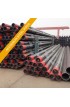
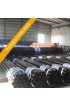
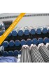
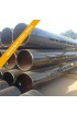
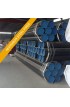
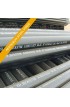
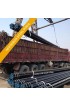
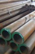
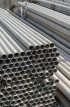
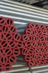
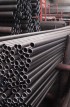
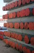
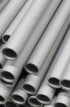
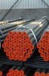
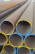
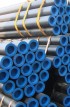
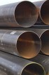
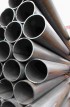
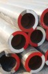
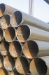
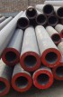
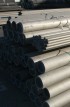
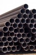
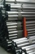
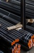
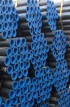
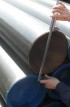
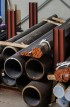
ASTM A554 / ASME SA554 / Welded Stainless Steel Mechanical Tubing supplier & distributor in India


ASTM A 554-88a / ASME SA 554
WELDED STAINLESS STEEL MECHANICAL TUBING
| 1. Scope 1.1 This specification covers welded stainless steel tubing for mechanical applications where appearance, mechanical properties, or corrosion resistance is needed. The grades covered are listed in table. 1.2 This specification covers as-welded or cold-reduced mechanical tubing in sizes to 16 in. (406.4mm) outside diameter, inclusive(for round tubing)and in wall thicknesses 0.020in.(0.51mm)and over. 1.3 Tubes shall be furnished in one of the following shapes as specified by the purchaser: round, square, rectangular, or special. 1.4 Supplementary requirements of an optional nature are provided and when desired shall be so stated in the order. 1.5 The values stated in inch-pound units are to be regarded as the standard. |
Table 1 Chemical Requirements
| Grade | Composition, % | |||||||||
| Carbon, max |
Manganese, max |
Phos- phorus, max |
Surfur, max |
Silicon, max |
Nickel | Chromium | Molybdenum | Titanium | Columbium +Tantalum |
|
| Austenitic | ||||||||||
| MT-301 | 0.15 | 2.00 | 0.040 | 0.030 | 1.00 | 6.0-8.0 | 16.0-18.0 | ... | ... | ... |
| MT-302 | 0.15 | 2.00 | 0.040 | 0.030 | 1.00 | 8.0-10.0 | 17.0-19.0 | ... | ... | ... |
| MT-304 | 0.08 | 2.00 | 0.040 | 0.030 | 1.00 | 8.0-11.0 | 18.0-20.0 | ... | ... | ... |
| MT-304L | 0.035A | 2.00 | 0.040 | 0.030 | 1.00 | 8.0-13.0 | 18.0-20.0 | ... | ... | ... |
| MT-305 | 0.12 | 2.00 | 0.040 | 0.030 | 1.00 | 10.0-13.0 | 17.0-19.0 | ... | ... | ... |
| MT-309S | 0.08 | 2.00 | 0.040 | 0.030 | 1.00 | 12.0-15.0 | 22.0-24.0 | ... | ... | ... |
| MT-309S-Cb | 0.08 | 2.00 | 0.040 | 0.030 | 1.00 | 12.0-15.0 | 22.0-24.0 | ... | ... | C |
| MT-310S | 0.08 | 2.00 | 0.040 | 0.030 | 1.00 | 19.0-22.0 | 24.0-26.0 | ... | ... | ... |
| MT-316 | 0.08 | 2.00 | 0.040 | 0.030 | 1.00 | 10.0-14.0 | 16.0-18.0 | 2.0-3.0 | ... | ... |
| MT-316L | 0.035A | 2.00 | 0.040 | 0.030 | 1.00 | 10.0-15.0 | 16.0-18.0 | 2.0-3.0 | ... | ... |
| MT-317 | 0.08 | 2.00 | 0.040 | 0.030 | 1.00 | 11.0-14.0 | 18.0-20.0 | 3.0-4.0 | ... | ... |
| MT-321 | 0.08 | 2.00 | 0.040 | 0.030 | 1.00 | 9.0-13.0 | 17.0-20.0 | ... | B | ... |
| MT-330 | 0.15 | 2.00 | 0.040 | 0.030 | 1.00 | 33.0-36.0 | 14.0-16.0 | ... | ... | ... |
| MT-347 | 0.08 | 2.00 | 0.040 | 0.030 | 1.00 | 9.0-13.0 | 117.0-20.0 | ... | ... | C |
| Ferritic | ||||||||||
| MT-429 | 0.12 | 1.00 | 0.040 | 0.030 | 1.00 | 0.50 max | 14.0-16.0 | ... | ... | ... |
| MT-430 | 0.12 | 1.00 | 0.040 | 0.030 | 1.00 | 0.50 max | 16.0-18.0 | ... | ... | ... |
| MT-430-Ti | 0.10 | 1.00 | 0.040 | 0.030 | 1.00 | 0.075 max | 16.0-19.5 | ... | 5 x C min. | ... |
| 0.75 max | ||||||||||
Table 2 Diameter, Wall,A and Ovality Toerances
(All Conditions Except Tubing with Bead Removed)
| NOTE 1 - Ovality is the difference between maximum and minimum outside diameters measured at any one cross section. There is no additional tolerance for ovality on tubes having a nominal wall thickness of more than 3% of the outside diameter. NOTE 2 - For sizes up to and including 5-in. (127.0-mm) outside diameter, an ovality tolerance of twice the tabular outside diameter tolerance spread shown is applied diamter readings should fall within the outside diameter tolerances as shown in this table. NOTE 3 - For sizes over 5-in. (127.0mm) to and including 16-in. (406.4-mm) outside diameter, when the specified wall thickness is 3% or less of the outside diameter, the ovality shall not exceed 1.5% of the specified outside diameter. |
| OD Size, in.(mm) | Wall Thickness | OD, ± | ||
| in. | mm | in. | mm | |
| Under 1/2 (12.7) | 0.020 to 0.049 | 0.51 to 1.24 | 0.004 | 0.10 |
| 1/2 to 1 (12.7 to 25.4) | 0.020 to 0.065 | 0.51 to 1.65 | 0.005 | 0.13 |
| 1/2 to 1(12.7 to 25.4) | over 0.065 to 0.134 | over 1.65 to 3.40 | 0.010 | 0.25 |
| Over 1 to 1/2 (25.4 to 38.1), incl | 0.025 to 0.065 | 0.64 to 1.65 | 0.008 | 0.20 |
| Over 1 to 1/2 (25.4 to 38.1), incl | over 0.065 to 0.134 | over 1.65 to 3.40 | 0.010 | 0.25 |
| Over 1 to 2 (25.4 to 38.1), incl | 0.025 to 0.049 | 0.64 to 1.65 | 0.010 | 0.25 |
| Over 1 to 2 (25.4 to 38.1), incl | over 0.049 to 0.083 | over 1.65 to 3.40 | 0.011 | 0.28 |
| Over 1 to 2 (25.4 to 38.1), incl | over 0.083 to 0.149 | 0.64 vo 1.24 | 0.012 | 0.30 |
| Over 2 to 2 1/2 (25.4 to 38.1), incl | 0.032 to 0.065 | over 1.24 to 2.11 | 0.012 | 0.30 |
| Over 2 to 2 1/2 (25.4 to 38.1), incl | over 0.065 to 0.109 | over 2.11 to 3.78 | 0.013 | 0.33 |
| Over 2 to 2 1/2 (25.4 to 38.1), incl | over 1.109 to 0.165 | 0.81 to 1.65 | 0.014 | 0.36 |
| Over 2 to 3 1/2 (25.4 to 38.1), incl | 0.032 to 0.165 | over 1.65 to 2.77 | 0.014 | 0.36 |
| Over 2 to 3 1/2 (25.4 to 38.1), incl | over 0.165 | over 2.77 to 4.19 | 0.020 | 0.51 |
| Over 3 to 5 1/2 (25.4 to 38.1), incl | 0.035 to 0.165 | 0.81 to 4.19 | 0.020 | 0.51 |
| Over 3 to 5 1/2 (25.4 to 38.1), incl | over 0.165 | over 4.19 | 0.025 | 0.34 |
| Over 5 to 16 1/2 (25.4 to 38.1), incl | all | all | 0.00125 in./in. or mm/mm of circumference | |
AWall tolerance ±10% of nominal wall thickness.
TABLE 3 Diameter, Wall,A and Ovality Tolerances for Tubing with Bead Removed
| NOTE 1 - Ovality is the difference between maximum and minimum outside diameters measured at any one cross section. There is no addifional tolerance for ovality on tubes having a nominal wall thickness of more than 3% of the outside diameter. NOTE 2 - An ovality allowance of twice the outside diameter tolerance, shown in this table, is applied one half plus and one haif minus to the outside diameter, for tubes having a nominal wall thickness of 3% or less of the outside diameter. The average of the maximum and minimum outside diameter readings should fall within the outside diameter tolerances of this table. NOTE 3 - Tubing may be specified to only two of the three following dimensions-outside diameter, inside diameter, or wall. |
| OD Size, in.(mm) | OD, ± | ID, ± | ||
| in. | mm | in. | mm | |
| Up to 3/32 (2.4), excl | 0.001 | 0.03 | 0.001 | 0.03 |
| 3/32 to 3/16(2.4 to 4.8), excl | 0.0015 | 0.038 | 0.0015 | 0.038 |
| 3/16 to 1/2 (4.8 to 12.7), excl | 0.003 | 0.08 | 0.005 | 0.13 |
| 1/2 to 1 (12.7 to 25.4), excl | 0.004 | 0.10 | 0.006 | 0.15 |
| 1 to 1 1/2 (25.4 to 38.1), excl | 0.005 | 0.13 | 0.007 | 0.18 |
| 1 1/2 to 2 (38.1 to 50.8), excl | 0.006 | 0.15 | 0.008 | 0.20 |
| 2 to 2 1/2 (50.8 to 63.5), excl | 0.007 | 0.18 | 0.010 | 0.25 |
| 2 1/2 to 3 1/2 (63.5 to 88.9), excl | 0.010 | 0.25 | 0.014 | 0.36 |
| 3 1/2 to 5 (88.9 to 127.0), incl | 0.015 | 0.38 | 0.020 | 0.51 |
| Over 5 to 6 (127.0 to 406.4), incl | 0.00125 in./in. or mm/mm of circumference |
0.0013 in./in. or mm/mm of circumference |
||
AWall tolerance is ±10% ofnominal wall thickness.
TABLE 4 Length Variations - Cut Length Tubes
| Length, ft (m) | Outside Diameter, in.(mm) |
Permissible Variations in Length, in. |
||
| OverA | Under | |||
| in. | mm | |||
| 4 (1.2) and under | up to 2(50.8), incl | 1/16 | 1.6 | 0 |
| over 2 to 4(50.8 to 101.6), incl | 3/32 | 2.4 | 0 | |
| over 4(101.6) | 1/8 | 3.2 | 0 | |
| Over4 to 10 (1.2 to 3.0), incl | up to 2(50.8), incl | 3/32 | 2.4 | 0 |
| over 2(50.8) | 1/8 | 3.2 | 0 | |
| Over 10 to 24 (3.0 to 7.3), incl | all sizes | 3/15 | 4.8 | 0 |
AFor all diameters in lengths over 24 ft (7.3m), an additional over tolerance of 1.8 in. (3.2 mm) for each 10 ft (3.0m)
or fraction thereof shall be permissible, up to a toleranceof 1/2 in. (12.7mm), max. determined from a product
analysis made by the tubular product manufacturer, shall conform to requirements specified.
When requested in the order or contract, a report of this analysis shall be furnished to the purchaser.
TABLE 5 Square and Rectangular Tubing
| Outside Dimension Tolerances | ||
| Largest Nominal Outside Dimension Across Flats, in.(mm) |
Wall Thickness,A in. (mm) |
±,in.(mm), across Flats, Convexity or Conscavity, incl |
| To 1 1/4(31.8), incl | all | 0.015(0.38) |
| Over 1 1/4 to 2 1/2 (31.8 to 63.8), incl | all | 0.020(0.51) |
| Over 2 1/2 to 5 1/2 (63.5 to 139.7), incl | all | 0.030(0.76) |
| Maximum Radii of Comers | ||
| Wall Thickness, in.(mm) | Radii of Comers, max, in.(mm) | |
| Over 0.020 to 0.049 (0.51 to 1.24), incl | 3/32 (2.4) | |
| Over 0.020 to 0.049 (0.51 to 1.24), incl | 1/8 (3.2) | |
| Over 0.020 to 0.049 (0.51 to 1.24), incl | 9/64 (3.6) | |
| Over 0.020 to 0.049 (0.51 to 1.24), incl | 3/16(4.8) | |
| Over 0.020 to 0.049 (0.51 to 1.24), incl | 13/34(5.2) | |
| Over 0.020 to 0.049 (0.51 to 1.24), incl | 7/32(5.6) | |
| Over 0.020 to 0.049 (0.51 to 1.24), incl | 1/4(6.4) | |
| Twist Tolerances | ||
| Largest Size, in. (mm) | Twist in 3 ft, max, in. (mm/m) |
|
| Under 1/2(12.7) | 0.050(1.4) | |
| 1/2 to 1 1/2(12.7 to 38.1), incl | 0.075(2.1) | |
| Over 1 1/2 to 2 1/2(38.1 to 63.5), incl | 0.095(2.6) | |
| Over 2 1/2 (63.5) | 0.125(3.5) | |
| Squareness of Sides | ||
| ±B = C x 0.006 where : B = tolerance for out-of-square, and C = length of longest side. |
||
| The straightness tolerance is 0.075 in. in 3 ft or 2.1 mm in 1 m using a 3-ft (1-m) straightedge and feeler gage. | ||
zAWall tolerance is ±10% of nominal wall thickness.
TABLE 7 Tensile Requirements (Round Annealed Condition)
| Grade | Tensile Strength, min |
Yield Strength, min |
Elongationa IN 2 IN. OR 50MM, MIN, % | ||
| ksi | MPa | ksi | MPa | ||
| MT 429 and MT 430 | 60 | 414 | 35 | 241 | 20 |
| MT-430-Ti | 60 | 414 | 30 | 207 | 20 |
| MT 304 L & 8 MT 316 L | 70 | 483 | 25 | 172 | 35 |
| All other austenitic steels | 75 | 517 | 30 | 207 | 35 |
AFor longitudinal strip tests, the width of the gage section shall be 1 in. (25.4mm) and a deduction of 1.75 percentage
points for austeniticc grades and 1.0 percentage points for MT 429 and MT 430 shall be permitted from the basic
minimum elongation for each 1/32-in. (0.79-mm) decrease in wall thickness below 5/16 in. (7.94mm).