
-
 $1.25
$1.25 -
 $1.25
$1.25 -
 $1.25
$1.25 -
 $1.25
$1.25 -
 $1.25
$1.25 -
 $1.25
$1.25 -
 $1.25
$1.25 -
 $1.25
$1.25 -
 $1.25
$1.25 -
 $1.25
$1.25 -
 $1.25
$1.25 -
 $1.25
$1.25 -
 $1.25
$1.25 -
 $1.25
$1.25 -
 $1.25
$1.25 -
 $1.25
$1.25 -
 $1.75
$1.75 -
 $2.00
$2.00 -
 $1.00
$1.00 -
 $1.25
$1.25 -
 $2.40
$2.40 -
 $4,500.00
 -
 $1,000.00
 -
 $2.00
$2.00 -
 $1.20
$1.20 -
 $1.25
$1.25 -
 $1.25
$1.25 -
 $1.25
$1.25 -
 $1.25
$1.25 -
 $1.25
$1.25 -
 $1.25
$1.25 -
 $0.00
$0.00 -
 $0.00
$0.00 -
 $1.25
$1.25 -
 $1.25
$1.25 -
 $1.25
$1.25 -
 $0.00
$0.00 -
 $1.25
$1.25 -
 $1.25
$1.25 -
 $1.25
$1.25 -
 $1.25
$1.25 -
 $1.25
$1.25 -
 $1.25
$1.25 -
 $1.25
$1.25 -
 $1.25
$1.25 -
 $1.25
$1.25 -
 $1.25
$1.25 -
 $1.25
$1.25 -
 $1.25
$1.25 -
 $1.25
$1.25 -
 $1.25
$1.25 -
 $1.25
$1.25 -
 $1.25
$1.25 -
 $1.25
$1.25 -
 $1.25
$1.25 -
 $1.25
$1.25 -
 $1.25
$1.25 -
 $1.25
$1.25 -
 $1.25
$1.25 -
 $1.25
$1.25 -
 $1.25
$1.25 -
 $1.25
$1.25 -
 $1.25
$1.25 -
 $0.00
$0.00
No products
Product successfully added to your shopping cart
There are 64 items in your cart. There is 1 item in your cart.
Categories
-
Carbon Steel Pipes & Tubes
- ASTM A106 SA106 Pipe
- ASTM A53 SA53 Pipe
- ASTM A135 SA135 Pipe
- ASTM A139 SA139 Pipe
- ASTM A179 SA179 Tubes
- ASTM A210 SA210 Tubes
- ASTM A333 SA333 Pipe
- ASTM A334 SA334 Pipe
- ASTM A500 SA500 Pipe
- ASTM A501 SA501 Pipe
- ASTM A512 SA512 Tube
- ASTM A513 SA513 Tube
- ASTM A517 SA517 Tube
- ASTM A519 SA519 Tube
- ASTM A671 SA671 Pipe
- ASTM A672 SA672 Pipe
- ASTM A252 Steel piling pipe
- Carbon Steel Seamless Pipe
- Carbon Steel Pipe Japan
- Carbon Steel Pipes Europe
- Carbon Steel Pipe China
-
Stainless Steel Pipes & Tubes
- Stainless Steel Tube, Tubing & Pipe
- ASTM A271 ASME SA271 Pipes/ Tubes
- ASTM A312 ASME SA312 Pipes/ Tubes
- ASTM A358 ASME SA358 Pipes/ Tubes
- ASTM A376 ASME SA376 Pipes/ Tubes
- ASTM A409 ASME SA409 Pipes/ Tubes
- ASTM A430 ASME SA430 Pipes/ Tubes
- ASTM A632 ASME SA632 Pipes/ Tubes
- ASTM A778 ASME SA778 Pipes/ Tubes
- ASTM A813 ASME SA813 Pipes/ Tubes
- ASTM A814 ASME SA814 Pipes/ Tubes
- ASTM A826 ASME SA826 Pipes/ Tubes
- ASTM A851 ASME SA851 Pipes/ Tubes
- ASTM A213 ASME SA213 Pipes/ Tubes
- ASTM A249 ASME SA249 Pipes/ Tubes
- ASTM A268 ASME SA268 Pipes/ Tubes
- ASTM A269 ASME SA269 Pipes/ Tubes
- ASTM A270 ASME SA270 Pipes/ Tubes
- ASTM A511 ASME SA511 Pipes/ Tubes
- ASTM A688 ASME SA688 Pipes/ Tubes
-
Alloy Steel Pipes & Tubes
-
Alloy Steel Tubes
- ASTM A213 T1 Alloy Steel Tube
- ASTM A213 T2 Alloy Steel Tube
- ASTM A213 T5 Alloy Steel Tube
- ASTM A213 T5b Alloy Steel Tube
- ASTM A213 T5c Alloy Steel Tube
- ASTM A213 T9 Alloy Steel Tube
- ASTM A213 T11 Alloy Steel Tube manufacturer and suppliers
- ASTM A213 T12 Alloy Steel Tube
- ASTM A213 T17 Alloy Steel Tube
- ASTM A213 T21 Alloy Steel Tube
- ASTM A213 T22 Alloy Steel Tube
- ASTM A213 T23 Alloy Steel Tube
- ASTM A213 T24 Alloy Steel Tube
- ASTM A213 T36 Alloy Steel Tube
- ASTM A213 T91 Alloy Steel Tube
- ASTM A213 T92 Alloy Steel Tube
- ASTM A213 T122 Alloy Steel Tube
- ASTM A213 T911 Alloy Steel Tube
- ASTM A513 Grade 8620 Alloy Steel Tube
- ASTM A513 Grade 4130 Alloy Steel Tube
- ASTM A513 Grade 4118 Alloy Steel Tube
- ASTM A513 Grade 4140 Alloy Steel Tube
- ASTM A513 Grade 8630 Alloy Steel Tube
-
Alloy Steel Pipes
- ASTM A335 P1 Alloy Steel Pipe
- ASTM A335 P2 Alloy Steel Pipe
- ASTM A335 P5 Alloy Steel Pipe
- ASTM A335 P5b Alloy Steel Pipe
- ASTM A335 P5c Alloy Steel Pipe
- ASTM A335 P9 Alloy Steel Pipe
- ASTM A335 P11 Alloy Steel Pipe Manufacturer & Suppliers
- ASTM A335 P12 Alloy Steel Pipe
- ASTM A335 P15 Alloy Steel Pipe
- ASTM A335 P21 Alloy Steel Pipe
- ASTM A335 P22 Alloy Steel Pipe Manufacturer and suppliers
- ASTM A335 P23 Alloy Steel Pipe
- ASTM A335 P24 Alloy Steel Pipe
- ASTM A335 P36 Alloy Steel Pipe
- ASTM A335 P91 Alloy Steel Pipe
- ASTM A335 P92 Alloy Steel Pipe
- ASTM A335 P122 Alloy Steel Pipe
- ASTM A335 P911 Alloy Steel Pipe
- Alloy Steel Pipe & Tube Specification
-
Alloy Steel Tubes
- Special Steel Grades Pipes & Tubes
- API 5L Pipe
- Titanium Pipes & Tubes
- Welded/ ERW Pipes
- Mild Steel Pipes & Tubes
- Ductile Iron Spun Pipe & Ductile Iron Flanged Pipe Cast
- Capillary Tube| Capillary Tubing
- Boiler Tube
- Heat exchanger tubes
- Cupro Nickel Tube
- Aluminium Tube
- Corten Steel Pipes & Tubes
- EIL Approved Pipes
- IBR Pipe/ Tube & Non IBR Pipe/ Tube
- Black Pipes
- Galvanised Steel Pipes/ GI Tubes
- SS Coiled Tubing/ Tubes
- SS Electropolished Pipes/ Tubes
- SS Rectangular Pipes/ Tubes
- SS Square Pipes/ Tubes
- Full comparison of the DIN and EN standards for pipes/tubes
- Stainless Steel Pipe grades comparison


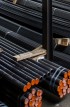
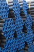
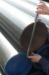
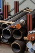
Surplus stock of Steel Pipes & Tubes:
Specialist in:
Offering best price on:
Widest inventory of:
SS,CS,Alloy Steel Pipe Prices
- » Steel Pipe/ Tube Price Iran
- » Steel Pipe/ Tube Price USA
- » Steel Pipe/ Tube Price India
- » Steel Pipe/ Tube Price China
- » Steel Pipe/ Tube Price Indonesia
- » Steel Pipe/ Tube Price UK
- » Steel Pipe/ Tube Price UAE
- » Steel Pipe/ Tube Price Malaysia
- » Steel Pipe/ Tube Price Singapore
- » Steel Pipe/ Tube Price South Korea
- » Steel Pipe/ Tube Price Saudi Arabia
- » Steel Pipe/ Tube Price Japan
- » Steel Pipe/ Tube Price Thailand
- » Steel Pipe/ Tube Price Bangladesh
- » Steel Pipe/ Tube Price Canada
- » Steel Pipe/ Tube Price Germany
- » Steel Pipe/ Tube Price Australia
- » Steel Pipe/ Tube Price Nigeria
- » Steel Pipe/ Tube Price Iraq
- » Steel Pipe/ Tube Price Turkey
- » Steel Pipe/ Tube Price Brazil
- » Steel Pipe/ Tube Price Vietnam
- » Steel Pipe/ Tube Price South Africa
- » Steel Pipe/ Tube Price Egypt
- » Steel Pipe/ Tube Price Bahrain
- » Steel Pipe/ Tube Price France
- » Steel Pipe/ Tube Price Mexico
- » Steel Pipe/ Tube Price Netherlands
- » Steel Pipe/ Tube Price Taiwan
- » Steel Pipe/ Tube Price Spain
- » Steel Pipe/ Tube Price Philippines
- » Steel Pipe/ Tube Price Pakistan
- » Steel Pipe/ Tube Price Kuwait
- » Steel Pipe/ Tube Price Norway
- » Steel Pipe/ Tube Price Oman
- » Steel Pipe/ Tube Price Qatar
- » Steel Pipe/ Tube Price Russia
- » Steel Pipe/ Tube Price Slovakia
- » Steel Pipe/ Tube Price Poland
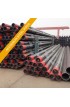
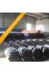
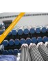
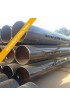
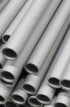
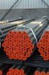
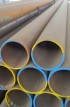
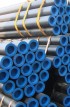
ASTM A791 / ASME SA791 / Welded Unannealde Ferritic Stainless Steel Tubing supplier & distributor in India


ASTM A 791-88 / ASME SA 791
WELDED UNANNEALED FERRITIC STAINLESS STEEL TUBING1
| This standard is issued under the fixed designation A 791; the number immediately following the designation indicates the year of original adoption or, in the case of revision, the year of last revision. A number in parentheses indicates the year of last reapproval. A superscript epsilon ( ε) indicates an editorial change since the last revision or reapproval. 1. Scope 1.1 This specification covers welded, unannealed, ferritic stainless steel tubing intended for high-temperature and corrosive serice where post-weld heat treatment is not necessary for corrosion resistance. These grades are com-monly known as the "straight-chromium" types and are characterized by being ferromagnetic. The high-chromium, ferritic alloys are sensitive to notch-brittleness on slow cooling to ordinary temperatures. These features should be recognized in the use of thest materials.The user requiring additional testing or examination is referred to the Supple-mentary Requirements or Ordering Information Section, or both. Users requiring a tubular product with post-weld heat treatment are referred to Specification A 2668 /A 268M. 1.2 The values stated in either inch-pound units or SI units are to be regarded separately as standard. Within the text, the SI units are shown in brackets. The values stated in each system are not exact equivalents; theerfore, each system must be used independently of the other. Combining values from the two systems may result in nonconformance with the specification. The inch-pound units shall apply unless the "M" designation of this specification is specified in the order. NOTE 1-For tubing smaller than 1/2 in. [12.7 mm] in outside diameter, the elongation values given for strip specimens in Table 1 shall apply. Mechanical property requirements do not apply to tubing smaller than 1/8 in. [3.2 mm]in outside diameter or with walls thinner than 0.015 in.[0.4mm]. |
Chemical composition
| Grade | Mfg. Process | Chemical composition(%) | ||||||||
| C | Si | Mn | P | S | Ni | Cr | Mo | Others | ||
| TP409 | E, W | 0.08Max | 1.00Max | 1.0Max | 0.045Max | 0.045Max | 0.50Max | 10.50~11.75 | - | Ti 6C~0.75 |
| TP439 | E, W | 0.07Max | 1.00Max | 1.00Max | 0.040Max | 0.030Max | 0.50Max | 17.00~19.00 | N 0.04Max Al 0.15Max | Ti 0.20+ 4(C+N)~1.10 |
| TPXM-27 | E, W | 0.01Max | 0.40Max | 0.40Max | 0.02Max | 0.02Max | 0.50Max | 25.0~27.0 | 0.75~1.50 | Cu 0.2Max N 0.015Max |
| TPXM-33 | E, W | 0.06Max | 0.75Max | 0.75Max | 0.040Max | 0.020Max | 0.50Max | 25.0~27.0 | Mo 0.75~1.50 Ti 7(C+N) 0.20Min 1.00Max | Cu 0.20Max N 0.040Max |
| 25-4-4 | E, W | 0.025Max | 0.75Max | 0.75Max | 0.040Max | 0.030Max | 3.5~4.5 | 24.5~26.0 | 3.5~4.2 | N 0.035Max Ti+Cb 0.2+4(C+N)~0.080 |
| 26-3-3 | E, W | 0.030Max | 1.00Max | 1.00Max | 0.040Max | 0.030Max | 1.0~3.50 | 25.0~28.0 | 3.0~3.50 | N 0.040Max Ti+Cb=6(C+N) 0.20Min 1.00Max |
| 29-4 | E, W | 0.010Max | 0.20Max | 0.30Max | 0.025Max | 0.15Max | 28.0~30.0 | 3.5~4.2 | - | Cu 0.15Max N 0.020Max |
| 29-4-2 | E, W | 0.010Max | 0.20Max | 0.30Max | 0.025Max | 0.20Max | 2.0~2.5 | 28.0~30.0 | 3.5~4.2 | Cu 0.15Max N 0.020Max |
| 18-2 | E, W | 0.030Max | 1.00Max | 1.00Max | 0.040Max | 1.00Max | 1.00Max | 28.0~30.0 | 3.60~4.20 | N 0.045Max (Ti+Cb)=6(C+N) 0.20Min 1.00Max |
| 29-4C | E, W | 1.00Max | 1.00Max | 1.00Max | 0.040Max | 1.00Max | 1.00Max | 17.5~2.50 | 1.75~2.50 | N 0.035Max (Ti+Cb)=6(C+N) 0.20Min 1.00Max |
Mechanical Properties
| Grade | Tensile Test MPa or N/mm2 | Remaks (Similar to JIS) | Possibility Temperature | |
| Min Yield point | Tensile Strength | |||
| TP409 | 205 | 380 | for High Temperature Service | - |
| TP439 | 205 | 415 | - | |
| TPXM-27 | 275 | 450 | - | |
| TPXM-33 | 310 | 415 | - | |
| 25-4-4 | 515 | 620 | - | |
| 26-3-3 | 450 | 585 | - | |
| 29-4 | 415 | 550 | - | |
| 29-4-2 | 415 | 550 | - | |
| 18-2 | 240 | 415 | - | |
| 29-4C | 415 | 515 | - | |
| 2. Referenced Documents 2.1 ASTM Standards : A 268/A 268M Specification for Seamless and Welded Ferritic and Martensitic Stainless Steel Tubing for General Service2 A 450/A 450M Specification for General Requirements for Carbon, Ferritic Alloy, and Austenitic Alloy Steel Tubes2 A 700 Practices for Packaging, Marking, and Loading Methods for Steel Products for Domestic Shipment3 A 763 Practices for Detecting Susceptibility to Intergranular Attack in Ferritic Stainless Steels4 -------------------------------------- 1This specification is under the jurisiction of ASTM Committee A-1 on Steel, Stainless Steel, and Prlated Alloys and is the direct responsibility of Subcommittee A01.10 on Pipe. Current edition approved July 15, 1991, Published September 1991. Originally published as A790-81. Last previous edition A791/A 791M-90 2Annual Book of ASTM Standards, Vol 01.01. 3Annual Book of ASTM Standards, Vol 01.05. 4Annual Book of ASTM Standards, Vol 01.03. |
TABLE 1 Tensile Requirements
| Grade | UNS Designation |
Tensile Strength, min, ksi [MPa] |
Yield Strength, min, ksi [MPa] |
ElongationA in 2 in. or 50mm min, % |
| TP 409 | S40900 | 55[380] | 30[205] | 20 |
| TP 439 | S40335 | 60[415] | 30[205] | 20 |
| TP XM-27 | S44627 | 65[450] | 40[275] | 18 |
| TP XM-33 | S44626 | 68[410] | 45[310] | 20 |
| 25-4-4 | S44635 | 90[620] | 75[515] | 12 |
| 26-3-3 | S44660 | 85[585] | 65[450] | 20 |
| 29-4 | S44700 | 80[550] | 60[415] | 20 |
| 29-4-2 | S44800 | 80[550] | 60[415] | 20 |
| 18-2 | S44400 | 60[415] | 35[240] | 20 |
| 29-4C | S44735 | 75[515] | 60[415] | 12 |
AFor longitudinal strip tests, a deduction of 0.60% for 29-4C, 0.90% for TPXM-27 and 1.00% for all other grades shall be made
from the basic minimum elongation for each 1/32 in. [0.8mm] decrease in wall thickness below 5/18 in.[8mm]. The following
table gives the computed minimum values :
| Wall Thickness in. | mm | Elongation in 2 in. or 50mm, min, % | ||
| 29-4C | TP XM-27 | All other Grades | ||
| 5/16[0.312] | 8 | 12 | 18 | 20 |
| 9/32[0.281] | 7.2 | 11 | 17 | 19 |
| 1/4[0.250] | 6.4 | 11 | 16 | 18 |
| 7/32[0.219] | 5.6 | 10 | 15 | 17 |
| 3/16[0.188] | 4.8 | 10 | 14 | 16 |
| 5/32[0.156] | 4 | 9 | 13 | 15 |
| 1/8[0.125] | 3.2 | 8 | 13 | 14 |
| 3/32[0.332] | 2.4 | 8 | 12 | 13 |
| 1/16[0.062] | 1.6 | 7 | 11 | 12 |
| 0.062 to 0.035, excl | 1.6 to 0.9 | 7 | 10 | 12 |
| 0.035 to 0.222, excl | 0.9 to 0.6 | 7 | 10 | 11 |
| 0.022 to 0.015, excl | 0.6 to 0.4 | 6 | 10 | 11 |
NOTE - The above taaable gives the computed minimum elongation values for each 1/32 in.[0.8mm] decrease in
wall thickness. Where the wall thickness lies between two values shown above, the minimum elongation value
shall be determined by the following equation : B Grade 29-4C E = 19.2t +6.00 [E = 0.75t + 6.00]
Grade TP XM-27 E = 28.8t + 9.00 [E = 1.13t + 9.00]
All Other Grades E = 32t + 10.00 [E = 12.5t +10.00] where : E = elongation in 2 in. or 50mm, %, and
t = actual thickness of specimens, in.[mm].
BCalculated elongation requirements shall be rounded to the nearest whole number.
TABLE 2 Chemical Requirements
| UNSS Grade |
S40900 TP 409 |
S40335 TP 439 |
S44627 TP XM-327 |
S44626 TP XM-33 |
S44635 25-4-4 |
S44660 26-3-3 |
S44700 29-4 |
S44800 29-4-2 |
S44735 29-4C |
S44500 18-2 |
| Composition, % | ||||||||||
| Carbon, max | 0.08 | 0.07 | 0.01C | 0.06 | 0.025 | 0.030 | 0.010 | 0.010 | 0.030 | 0.025 |
| Manganese,max | 1.0 | 1.00 | 0.40 | 0.75 | 1.00 | 1.00 | 0.30 | 0.30 | 1.00 | 1.00 |
| Phosphours,max | 0.045 | 0.040 | 0.02 | 0.040 | 0.040 | 0.040 | 0.025 | 0.025 | 0.040 | 0.040 |
| Sulfur,max | 0.045 | 0.030 | 0.020.40 | 0.020 | 0.030 | 0.030 | 0.020 | 0.020 | 0.030 | 0.030 |
| Siicon,max | 1.00 | 1.00 | 0.5Dmax | 0.75 | 0.75 | 1.00 | 0.20 | 0.20 | 1.00 | 1.00 |
| Nickel | 0.50max | 0.50max | 25.0-27.5 | 0.50max | 3.5-4.5 | 1.0-3.50 | 2.0-2.5 | 2.0-2.5 | 1.00max | 1.00max |
| Chromium | 10.50-11.75 | 17.00-19.00 | 0.75-1.50 | 25.0-27.0 | 24.5-26.0 | 25.0-28.0 | 28.0-30.0 | 28.0-30.0 | 28.00-30.00 | 17.5-19.5 |
| Molybdenum | ... | ... | ... | 0.75-1.00 | 3.5-4.5 | 3.0-4.0 | 3.5-4.2 | 3.5-4.2 | 3.60-4.20 | 1.75-2.50 |
| Aluminum | ... | 0.15max | 0.2max | ... | ... | ... | ... | ... | ... | ... |
| Copper | ... | ... | 0.015max | 0.20max | ... | ... | 0.15max | 0.15max | ... | ... |
| Nitrogen | ... | 0.04max | ... | 0.040max | 0.035max | 0.040max | 0.020maxB | 0.020maxc | 0.045max | 0.035max |
| Titanium | 6 x C min; 0.75 max |
0.20+4(C+N) min; 1.10max |
7X(C+N) but no less than 0.20min 1.00max |
(Ti+Cb)= 0.20+4 (C+N) min;0.80 max |
(Ti+Cb)= 6 X(C+N) but no less than 0.20min 1.00max |
(Ti+Cb)= 6 X(C+N) but no less than 0.20min 1.00max |
(Ti+Cb)= 0.20+4 (C+N) min;0.80 max |
|||
| Columbium | ... | ... | 0.05-0.20 | ... | ... | ... | ... | ... | ... | ... |
ANew designation established in accordance with ASTM E 527 and SAE J1086, Practice for Numbering Metals and
Alloys (UNS). BCarbon plus nitrogen = 0.025max. CFor small diameter or thin walls, or both, tubing, where many
drawing passes are required, a carbon maximum of 0.015% is necessary. Small outside diameter tubes are defined
as those less than 0.500 in. [12.7mm] in outside diameter and light wall tubes as those less than 0.049 in.[1.2mm]
in everage wall thickness (0.040 in. [1mm]. DNickel plus copper.
TABLE 3 Hardness Requirements
| Grade | Brinell Hardness, max | Rockwell Hardness, B Scale, max |
| TP 409 | 207 | 95 |
| TP 439 | 207 | 95 |
| TP XM-27 | 241 | 100 |
| TP XM-33 | 241 | 100 |
| 25-4-4 | ... | 30 |
| 26-3-3 | 265 | 25A |
| 29-4 | 241 | 100 |
| 29-4-2 | 241 | 100 |
| 18-2 | 217 | 95 |
| 29-4C | ... | 25A |
ARockwell hardness, C scale. NOTE 2 - For product analysis and flange requirements, the term lot applies to all tubes,
prior to cutting, of the same nominal size and wall thickness that are produced from the same heat of steel.
The number of tubes of the same size and from the same heat in a lot shall be determined from the size of the tubes as
prescribed in Table 4. NOTE 3 - For tensile and hardness test requirements, the term lot applies to all tubes,
prior to cutting, of the saaa8.1 The material shal conform to the tensile properties prescribed in Table 2.
TABLE4 Number of Tubes in a Lot
| Size of Tube | Size of Lot |
| 2 in.[50.8mm] and over in outside diameter and 0.200 in. [5.1mm] and over in wall thickness | not more than 50 tubes |
| Less than 2 in. [50.8mm] but over 1 in.[25.4mm] in outside diameter and under 0.200 in. [5.1mm] in wall thickness |
not more than 75 tubes |
| 1 in.[25.4mm] or less in outside diameters | not more than 125 tubes |
10.2 The permissible variatioins in outside diameter given in Table 5 are not sufficient to provide for ovality in thin-walled tubes,
as defined in the Table. In such tubes, the maximum and minimum diameters at any cross section shall deviate from the
nominal diameter by no more than twice the permissible variation in outside diameter given in Table 5; however, the mean
diameter at that cross section must still be within the given permissible variation.
TABLE 5 Permissible Variations in Dimensions
| Group | Size, Outside Dianmeter, in. [mm] |
Permissible Variations in Outside Diameter, in.[mm] |
Permissible Variations in Wall Thickness, % |
Permissible Variations in Cut Lneght, in.[mm]A |
Thin Walled TubesC | |
| 1 | Up to 1/2[12.7], excl | ±0.0055 [0.13] | ±15 | 1/8 [3] | 0 | ... |
| 2 | 1/2 to 1 1/2[12.7 to 38.1], excl | ±0.0005 [0.13] | ±10 | 1/8 [3] | 0 | less than 0.065 in. [1.6mm] nominal |
| 3 | 1 1/2 to 3 1/2[38.1 to 88.9], excl | ±0.0010 [0.25] | ±10 | 3/16 [5] | 0 | less than 0.095in. [2.4mm] nominal |
| 4 | 3 1/2 to 5 1/2[88.9 to 139.7], excl | ±0.0015 [0.38] | ±10? | 3/16 [5] | 0 | less than 0.150 in. [3.8mm] nominal |
| 5 | 5 1/2 to 8[139.7 to 203.2], incl | ±0.0030 [0.76] | ±10 | 3/16 [5] | 0 | less than 0.150 in. [3.8mm] nominal |
AThese tolerances apply to cut lengths up to and including 24 ft [7.3m]. For lengths over 24 ft [7.3m] andn additional over
tolerance of 1/8 in.[3mm] for each 10 ft [3.0m] or fraction thereof shall be permissible up to a maximum of 1/2 in.[3mm].