
My Cart -
64
Product
Products
$5,575.35
Empty
-
 $1.25
$1.25 -
 $1.25
$1.25 -
 $1.25
$1.25 -
 $1.25
$1.25 -
 $1.25
$1.25 -
 $1.25
$1.25 -
 $1.25
$1.25 -
 $1.25
$1.25 -
 $1.25
$1.25 -
 $1.25
$1.25 -
 $1.25
$1.25 -
 $1.25
$1.25 -
 $1.25
$1.25 -
 $1.25
$1.25 -
 $1.25
$1.25 -
 $1.25
$1.25 -
 $1.75
$1.75 -
 $2.00
$2.00 -
 $1.00
$1.00 -
 $1.25
$1.25 -
 $2.40
$2.40 -
 $4,500.00
 -
 $1,000.00
 -
 $2.00
$2.00 -
 $1.20
$1.20 -
 $1.25
$1.25 -
 $1.25
$1.25 -
 $1.25
$1.25 -
 $1.25
$1.25 -
 $1.25
$1.25 -
 $1.25
$1.25 -
 $0.00
$0.00 -
 $0.00
$0.00 -
 $1.25
$1.25 -
 $1.25
$1.25 -
 $1.25
$1.25 -
 $0.00
$0.00 -
 $1.25
$1.25 -
 $1.25
$1.25 -
 $1.25
$1.25 -
 $1.25
$1.25 -
 $1.25
$1.25 -
 $1.25
$1.25 -
 $1.25
$1.25 -
 $1.25
$1.25 -
 $1.25
$1.25 -
 $1.25
$1.25 -
 $1.25
$1.25 -
 $1.25
$1.25 -
 $1.25
$1.25 -
 $1.25
$1.25 -
 $1.25
$1.25 -
 $1.25
$1.25 -
 $1.25
$1.25 -
 $1.25
$1.25 -
 $1.25
$1.25 -
 $1.25
$1.25 -
 $1.25
$1.25 -
 $1.25
$1.25 -
 $1.25
$1.25 -
 $1.25
$1.25 -
 $1.25
$1.25 -
 $1.25
$1.25 -
 $0.00
$0.00
No products
Free shipping!
Shipping
$5,575.35
Total
Product successfully added to your shopping cart
Quantity
Total
There are 64 items in your cart. There is 1 item in your cart.
Total products
(tax incl.)
$5,575.35
Total shipping (tax incl.)
Free shipping!
Total
(tax incl.)
$5,575.35
Categories
-
Carbon Steel Pipes & Tubes
- ASTM A106 SA106 Pipe
- ASTM A53 SA53 Pipe
- ASTM A135 SA135 Pipe
- ASTM A139 SA139 Pipe
- ASTM A179 SA179 Tubes
- ASTM A210 SA210 Tubes
- ASTM A333 SA333 Pipe
- ASTM A334 SA334 Pipe
- ASTM A500 SA500 Pipe
- ASTM A501 SA501 Pipe
- ASTM A512 SA512 Tube
- ASTM A513 SA513 Tube
- ASTM A517 SA517 Tube
- ASTM A519 SA519 Tube
- ASTM A671 SA671 Pipe
- ASTM A672 SA672 Pipe
- ASTM A252 Steel piling pipe
- Carbon Steel Seamless Pipe
- Carbon Steel Pipe Japan
- Carbon Steel Pipes Europe
- Carbon Steel Pipe China
-
Stainless Steel Pipes & Tubes
- Stainless Steel Tube, Tubing & Pipe
- ASTM A271 ASME SA271 Pipes/ Tubes
- ASTM A312 ASME SA312 Pipes/ Tubes
- ASTM A358 ASME SA358 Pipes/ Tubes
- ASTM A376 ASME SA376 Pipes/ Tubes
- ASTM A409 ASME SA409 Pipes/ Tubes
- ASTM A430 ASME SA430 Pipes/ Tubes
- ASTM A632 ASME SA632 Pipes/ Tubes
- ASTM A778 ASME SA778 Pipes/ Tubes
- ASTM A813 ASME SA813 Pipes/ Tubes
- ASTM A814 ASME SA814 Pipes/ Tubes
- ASTM A826 ASME SA826 Pipes/ Tubes
- ASTM A851 ASME SA851 Pipes/ Tubes
- ASTM A213 ASME SA213 Pipes/ Tubes
- ASTM A249 ASME SA249 Pipes/ Tubes
- ASTM A268 ASME SA268 Pipes/ Tubes
- ASTM A269 ASME SA269 Pipes/ Tubes
- ASTM A270 ASME SA270 Pipes/ Tubes
- ASTM A511 ASME SA511 Pipes/ Tubes
- ASTM A688 ASME SA688 Pipes/ Tubes
-
Alloy Steel Pipes & Tubes
-
Alloy Steel Tubes
- ASTM A213 T1 Alloy Steel Tube
- ASTM A213 T2 Alloy Steel Tube
- ASTM A213 T5 Alloy Steel Tube
- ASTM A213 T5b Alloy Steel Tube
- ASTM A213 T5c Alloy Steel Tube
- ASTM A213 T9 Alloy Steel Tube
- ASTM A213 T11 Alloy Steel Tube manufacturer and suppliers
- ASTM A213 T12 Alloy Steel Tube
- ASTM A213 T17 Alloy Steel Tube
- ASTM A213 T21 Alloy Steel Tube
- ASTM A213 T22 Alloy Steel Tube
- ASTM A213 T23 Alloy Steel Tube
- ASTM A213 T24 Alloy Steel Tube
- ASTM A213 T36 Alloy Steel Tube
- ASTM A213 T91 Alloy Steel Tube
- ASTM A213 T92 Alloy Steel Tube
- ASTM A213 T122 Alloy Steel Tube
- ASTM A213 T911 Alloy Steel Tube
- ASTM A513 Grade 8620 Alloy Steel Tube
- ASTM A513 Grade 4130 Alloy Steel Tube
- ASTM A513 Grade 4118 Alloy Steel Tube
- ASTM A513 Grade 4140 Alloy Steel Tube
- ASTM A513 Grade 8630 Alloy Steel Tube
-
Alloy Steel Pipes
- ASTM A335 P1 Alloy Steel Pipe
- ASTM A335 P2 Alloy Steel Pipe
- ASTM A335 P5 Alloy Steel Pipe
- ASTM A335 P5b Alloy Steel Pipe
- ASTM A335 P5c Alloy Steel Pipe
- ASTM A335 P9 Alloy Steel Pipe
- ASTM A335 P11 Alloy Steel Pipe Manufacturer & Suppliers
- ASTM A335 P12 Alloy Steel Pipe
- ASTM A335 P15 Alloy Steel Pipe
- ASTM A335 P21 Alloy Steel Pipe
- ASTM A335 P22 Alloy Steel Pipe Manufacturer and suppliers
- ASTM A335 P23 Alloy Steel Pipe
- ASTM A335 P24 Alloy Steel Pipe
- ASTM A335 P36 Alloy Steel Pipe
- ASTM A335 P91 Alloy Steel Pipe
- ASTM A335 P92 Alloy Steel Pipe
- ASTM A335 P122 Alloy Steel Pipe
- ASTM A335 P911 Alloy Steel Pipe
- Alloy Steel Pipe & Tube Specification
-
Alloy Steel Tubes
- Special Steel Grades Pipes & Tubes
- API 5L Pipe
- Titanium Pipes & Tubes
- Welded/ ERW Pipes
- Mild Steel Pipes & Tubes
- Ductile Iron Spun Pipe & Ductile Iron Flanged Pipe Cast
- Capillary Tube| Capillary Tubing
- Boiler Tube
- Heat exchanger tubes
- Cupro Nickel Tube
- Aluminium Tube
- Corten Steel Pipes & Tubes
- EIL Approved Pipes
- IBR Pipe/ Tube & Non IBR Pipe/ Tube
- Black Pipes
- Galvanised Steel Pipes/ GI Tubes
- SS Coiled Tubing/ Tubes
- SS Electropolished Pipes/ Tubes
- SS Rectangular Pipes/ Tubes
- SS Square Pipes/ Tubes
- Full comparison of the DIN and EN standards for pipes/tubes
- Stainless Steel Pipe grades comparison


Surplus stock of Steel Pipes & Tubes:
Specialist in:
Offering best price on:
Widest inventory of:
SS,CS,Alloy Steel Pipe Prices
- » Steel Pipe/ Tube Price Iran
- » Steel Pipe/ Tube Price USA
- » Steel Pipe/ Tube Price India
- » Steel Pipe/ Tube Price China
- » Steel Pipe/ Tube Price Indonesia
- » Steel Pipe/ Tube Price UK
- » Steel Pipe/ Tube Price UAE
- » Steel Pipe/ Tube Price Malaysia
- » Steel Pipe/ Tube Price Singapore
- » Steel Pipe/ Tube Price South Korea
- » Steel Pipe/ Tube Price Saudi Arabia
- » Steel Pipe/ Tube Price Japan
- » Steel Pipe/ Tube Price Thailand
- » Steel Pipe/ Tube Price Bangladesh
- » Steel Pipe/ Tube Price Canada
- » Steel Pipe/ Tube Price Germany
- » Steel Pipe/ Tube Price Australia
- » Steel Pipe/ Tube Price Nigeria
- » Steel Pipe/ Tube Price Iraq
- » Steel Pipe/ Tube Price Turkey
- » Steel Pipe/ Tube Price Brazil
- » Steel Pipe/ Tube Price Vietnam
- » Steel Pipe/ Tube Price South Africa
- » Steel Pipe/ Tube Price Egypt
- » Steel Pipe/ Tube Price Bahrain
- » Steel Pipe/ Tube Price France
- » Steel Pipe/ Tube Price Mexico
- » Steel Pipe/ Tube Price Netherlands
- » Steel Pipe/ Tube Price Taiwan
- » Steel Pipe/ Tube Price Spain
- » Steel Pipe/ Tube Price Philippines
- » Steel Pipe/ Tube Price Pakistan
- » Steel Pipe/ Tube Price Kuwait
- » Steel Pipe/ Tube Price Norway
- » Steel Pipe/ Tube Price Oman
- » Steel Pipe/ Tube Price Qatar
- » Steel Pipe/ Tube Price Russia
- » Steel Pipe/ Tube Price Slovakia
- » Steel Pipe/ Tube Price Poland
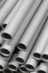
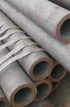
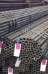
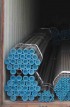
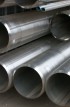
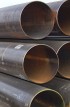
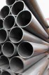
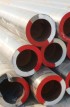
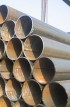
ASTM B210 / ASME SB210 / Aluminum and Aluminum-Alloy Drawn Seamless Tubes supplier & distributor in India


ASTM B-210 / ASME SB-210
SPECIFIATION FOR ANLUMINUM AND ALUMINUM-ALLOY DRAWN SEAMLESS TUBES
| 1.Scope 1.1 This specificatoin covers aluminum and aluminum-alloy darwn seamless tubes in atraight ienhts and coils for general purpose and pressure applicatoins in alloys (Note 2), temperas, and thicknesses shown in Table 2. Coiled tubes ae generally available only as rond tubes with a wall thickness not exceeding 0.083 in. and only in nonheat-treatable alloys. 1.2 Alloy and temper designation are in accordance with ANSI H35.1. The equivalent Unified Numbering Systerm alloy designations are those of Table 1 preceded 1100 in accordance with Pratice E 527. NOTE 1 ? See Specification SB-234 for alumium-alloy drawn seamless tubes for ocndenses and heat exchange: and Specification SB0241/SB-241M for aluminum-alloy seamless pipe and seamless extruded tube. NOTE 2 ? Throught this specification, use of the tem alloy in the gneral sense includes aluminum as well as aluminum alloy. 1.3 A compelete metric companin to Specificatoin B 210 has been developed ? Specification B 210M: Therefore, no matric equivalents are presenred in this specification. 1.4 For acceptance criteria for inclusion of new aluminum alloys in this specification, see Annex A2. |
TABLE1 CHEMICAL COMPOSTION LIMITS [NOTES(1), (2), (3)]
| Alloy | Silicon | Iron | Copper | Manganese | Magnesium | Chromium | zine | Titanium | Other Elements[Note(4)] | Aluminum, Min. | |
| Each | Total [Note(5)] | ||||||||||
| 1060 | 0.25 | 0.35 | 0.05 | 0.03 | 0.03 | ... | 0.05 | 0.03 | 0.03[Note(6)] | ... | 99.60min[Note(7)] |
| 3003 | 0.6 | 0.7 | 0.05-0.20 | 1.0-1.5 | ... | ... | 0.10 | ... | 0.05 | 0.15 | Remainder |
| Aiclad 3003[Note(8)] | ... | ... | ... | ... | ... | ... | ... | ... | ... | ... | ... |
| 5052 | 0.25 | 0.40 | 0.10 | 0.10 | 2.2-2.8 | 0.15-0.35 | 0.10 | ... | 0.05 | 0.15 | Remainder |
| 5154 | 0.25 | 0.40 | 0.10 | 0.10 | 3.1-3.9 | 0.15-0.35 | 0.20 | 0.20 | 0.05 | 0.15 | Reaminder |
| 6061 | 0.40-0.8 | 0.7 | 0.15-0.40 | 0.15 | 0.8-1.2 | 0.04-0.35 | 0.25 | 0.15 | 0.05 | 0.15 | Remainder |
| 6063 | 0.20-0.6 | 0.35 | 0.10 | 0.10 | 0.45-0.9 | 0.10 | 0.10 | 0.10 | 0.05 | 0.15 | Remainder |
| 7072 cladding [Note(9)] |
0.7Si+Fe | 0.10 | 0.10 | 0.10 | ... | 0.8-1.3 | ... | 0.05 | 0.15 | Reamainder | |
| NOTE: (1) Limits are in weight percent maximum unless shown as a range or otherwise stanted. (2) Analysis shtaal regularly be made only for the elements specified in this Table. If, however, the presence of other elements is suspected or indicated in amounts greater than the specified limits, further analysis shall be made to etermine that these elsments are not percentin excess of the specified limits (3) for purposes of detemining conformance to these limits, an ovserved value or a calculated value vbtained from analysis shall be rounded to the nearest unit in the last right-hand place of figures used in expressing the specified limit, in accordance with the rounding-off method of Practice E 29. (4) Include listed elements for which no specific limit is shown. (5) Other elements- Total shall be the sum of unspecified metallic elements 0.010% or more, rounded to the second decimal before determining the sum. (6) Vanadium 0.05% max. (7) The aluminum content shalll be calculated by subtracting from 100.00% the sum of alll metallic elements present in amounts of 0.010% or more, rounded to the second decimal before determining the sum. (8) Alloy clad with Alloy 7072. (9) Composition of cladding alloy as applied during the couse of manufacture. The samples from finishged thbe shall not be required to conform to these limits. |
TABLE2 TENSILE PROPERTY LIMITS [NOTE(1), (2)]
| Temper | Specified Wall Thickness [Note(3)], in | Tensile Strength, ksi | Yield Strength [Note(4)](0.2% Offset), Min, ksi | Elongation in 2 in or 4×Dia [Note(5)], Min., % | ||
| Min. | Max. | Full-Section Specimen | Cut-Out Specimen | |||
| Aluminum 1060 [Note(6)] | ||||||
| O | 0.018-0.500 | 8.5 | 13.5 | 2.5 | ... | ... |
| H14 | 0.018-0.500 | 12.0 | ... | 10.0 | ... | ... |
| H113[Note(7)] | 0.018-0.500 | 8.5 | ... | 2.5 | ... | ... |
| Alloy 3003[Note(6)] | ||||||
| O | 0.010-0.024 | 14.0 | 19.0 | 5.0 | ... | ... |
| 0.025-0.049 | 14.0 | 19.0 | 5.0 | 30 | 20 | |
| 0.050-0.259 | 14.0 | 19.0 | 5.0 | 35 | 25 | |
| 0.260-0.500 | 14.0 | 19.0 | 5.0 | ... | 30 | |
| H12 | 0.010-0.500 | 17.0 | ... | 12.0 | ... | ... |
| H14 | 0.010-0.024 | 20.0 | ... | 17.0 | 3 | ... |
| 0.025-0.049 | 20.0 | ... | 17.0 | 5 | 3 | |
| 0.050-0.259 | 20.0 | ... | 17.0 | 5 | 4 | |
| 0.260-0.500 | 20.0 | ... | 17.0 | ... | ... | |
| H18 | 0.010-0.024 | 27.0 | ... | 24.0 | 2 | ... |
| 0.025-0.049 | 27.0 | ... | 24.0 | 3 | 2 | |
| 0.050-0.259 | 27.0 | ... | 24.0 | 5 | 3 | |
| 0.260-0.500 | 27.0 | ... | 24.0 | ... | ... | |
| H113[Note(7)] | 0.010-0.0500 | 14.0 | ... | 5.0 | ... | ... |
| Alloy Alclad 30003 | ||||||
| O | 0.010-0.024 | 13.0 | 19.0 | 4.5 | ... | ... |
| 0.025-0.049 | 13.0 | 19.0 | 4.5 | 20 | 20 | |
| 0.050-0.259 | 13.0 | 19.0 | 4.5 | 35 | 25 | |
| 0.260-0.500 | 13.0 | 19.0 | 4.5 | ... | 30 | |
| H14 | 0.010-0.024 | 19.0 | ... | 16.0 | ... | ... |
| 0.025-0.049 | 19.0 | ... | 16.0 | 5 | ... | |
| 0.050-0.259 | 19.0 | ... | 16.0 | 8 | 4 | |
| 0.260-0.500 | 19.0 | ... | 16.0 | .. | ... | |
| H18 | 0.010-0.500 | 26.0 | ... | 23.0 | ... | ... |
| H113[Note(7)] | 0.050-0.500 | 13.0 | ... | 4.5 | ... | ... |
| Alloy 5052[Note(6)] | ||||||
| O[Note(6)] | 0.010-0.024 | 13.0 | 19.0 | 4.5 | ... | ... |
| H32 | 0.018-0.450 | 31.0 | .. | 23.0 | ... | ... |
| H34 | 0.018-0.450 | 34.0 | ... | 26.0 | ... | ... |
| Alloy 5154[Note(6)] | ||||||
| O | 0.010-0.450 | 30.0 | 41.0 | 11.0 | 10 | 10 |
| H34 | 0.010-0.450 | 39.0 | ... | 29.0 | 5 | 5 |
| Alloy 6061 | ||||||
| T4 | 0.025-0.049 | 30.0 | ... | 16.0 | 16 | 14 |
| 0.050-0.259 | 30.0 | ... | 16.0 | 18 | 16 | |
| 0.260-0.500 | 30.0 | ... | 16.0 | 20 | 18 | |
| T6 | 0.025-0.049 | 42.0 | ... | 35.0 | 10 | 8 |
| 0.050-0.259 | 42.0 | ... | 35.0 | 12 | 10 | |
| 0.260-0.500 | 42.0 | ... | 35.0 | 14 | 12 | |
| Alloy 6063 | ||||||
| T6 | 0.025-0.049 | 33.0 | ... | 28.0 | 12 | 8 |
| 0.050-0.259 | 33.0 | ... | 28.0 | 14 | 10 | |
| 0.260-0.500 | 33.0 | ... | 28.0 | 16 | 12 | |
TABLE3 MINIMUM OUTSIDE DIAMETER FLATTENIG FACTOR
| Alloy | Temper | Wall Thickness, in. | Min. Dia Flattening Factor,F |
| 3003 | O | 0.025-0.500 | 2 |
| H12 | 0.025-0.500 | 3 | |
| H14 | 0.25-0.500 | 6 | |
| 5052 | O | 0.010-0.450 | 3 |
| H32 | 0.010-0.450 | 6 | |
| H34 | 0.010-0.450 | 8 | |
| 6061 | T4 | 0.025-0.500 | 6 |
| T6 | 0.025-0.500 | 8 |
TABLE4 MIINMUM BEND FACTOR
| Alloy | Temper | Wall Thickness, in. | Min. Bend Factor, N |
| 5052 | O | 0.010-0.249 | 1 |
| H32 | 0.010-0.249 | 4 | |
| H34 | 0.010-0.249 | 6 | |
| 6061 | T4 | 0.025-0.500 | 4 |
| T6 | 0.025-0.500 | 6 |
TABLE5 FLARE DIMENSIONS[NOTE(10], in.
| Nomial OD | Expanded OD, Min. | Nominal OD | Expanded OD, Min. |
| 0.125 | 0.224 | 0.750 | 0.937 |
| 0.188 | 0.302 | 1.000 | 1.187 |
| 0.250 | 0.359 | 1.250 | 1.500 |
| 0.312 | 0.421 | 1.500 | 1.721 |
| 0.375 | 0.484 | 1.750 | 2.106 |
| 0.500 | 0.656 | 2.000 | 2.356 |
| 0.625 | 0.781 |
TABLE6 INDEX TO TABLES OF PERMISSIBLE VARIATIONS OF ANSI H35.2
| Table No. | Title |
| 11.1 | Diameter, Round Tube |
| 11.2 | Width and Depth, Square, Rectangular, Hexagonal, and Octagonal Tube |
| 11.3 | Diameter Oval, Elliptical, and streamline Tube |
| 11.4 | Corner Radii |
| 11.5 | Wall Thickness, Round and Other-Rgan-Round Tube |
| 11.6 | Straightness |
| 11.7 | Twist |
| 11.8 | Length |
| 11.9 | Flatness,(Flat Surfaces) Other-Tan_Round Tube |
| 11.10 | Squareness of Cut Ends |
| 11.11 | Angularity |
| 11.12 | Surface Roughness |
| 11.13 | Dents |
Material Comparison Tables (ASTM →KS, JIS, DIN, BS, NBN, NF, UNI)
| ASTMSTANDARD | KOREA/JAPANES | GERMAN | BRITISH | ISO | ||||||
| KS/JIS Symbol | KS/JIS Numbe | Remarks | DIN Type | B.S Number | B.S Grade | Remarks | ISO Type | ISO Number | Ramarks | |
| B 210 Aluminium-Alloy Drawn Seamless Tubes | ||||||||||
| A1070PE/A1070TD | D6761/H4080 | |||||||||
| A1050PE/A1050TD | D6761/H4080 | 1471 | 1050A | |||||||
| 100 | A1100PD/A1100TD | D6761/H4080 | A199.0Cu | 209 | ||||||
| A1200PD/A1200TD | D6761/H4080 | A199 | 1747 | 1471 | 1200 | A199.0 | ||||
| A2017PD/A2017TD | D6761/H4080 | AlCuMg1 | 1747 | Al-Cu4MgSi | ||||||
| 20024 | A2024PD/A2024TD | D6761/H4080 | AlCuMg2 | 1747 | ||||||
| 3003 | A3003PD/A3003TD | D6761/H4080 | Al-Mg1Cu | |||||||
| A3203PD/A3203TD | D6761/H4080 | |||||||||
| 5052 | A5052PD/A5052TD | D6761/H4080 | Al-Mg2.5 | |||||||
| 5154 | A5154PD/A5154TD | D6761/H4080 | ||||||||
| A5056PD/A5056TD | D6761/H4080 | AlMg5 | 1747 | 1471 | 5154A | |||||
| 5083 | A5083PD/A5083TD | D6761/H4080 | AlMg4.5Mn | 1747 | Al-Mg4.5Cu | |||||
| 6061 | A6061PD/A9061TD | D6761/H4080 | 1471 | 5083 | ||||||
| 6063 | A6063PD/A6063TD | D6761/H4080 | 1471 | 6061 | Al-MgSi | |||||
| 7075 | A7075PD/A7075TD | D6761/H4080 | AlZnMg1.5 | 1747 | 1471 | 6063 | Al-Zn5.5MgCu | |||