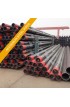
ASTM B467 / ASME SB467 / Welded Copper Nickel Pipe supplier & distributor in India
ASTM B-467 / ASME SB-467
1.Scope
Copper Alloy UNS No.A
Previously Used Deignation
Nominal Composition. %
Copper
Nickel
C70600
706
90
10
C71500
715
70
30
Copper Alloy
Composition, %
CopperB
Lead,D
Iron
Zinc,Dmax
Manganese, max
Sulfur, max
Phosphorus, max
Other Named Elements
C70600
remainder
9.0-11.0
0.05
1.0-1.8
1.0
1.0
0.02
0.02
D
C71500
remainder
29.0-33.0
0.05
0.40-1.0
1.0
1.0
0.02
0.02
D
Copper Alloy UNS No.
Outside Diameter, in.
Tensile Strength min, ksi
Yield Strength at 0.5% Extension Under Load, min, ksi
Elongation in 2 in. min, %
C70600
up to 4 1/2 incl
40
15
25.0
over 4 1/2
38
13
25.0
C71500
up to 4 1/2 incl
50
20
30.0
over 4 1/2
45
15
30.0
Copper Alloy UNS No.
Outside Diamter, in.
Tensile Strength min, ksiA
Yield Strength at 0.5% Extension Under Load, min, ksiA
Elongation in 2 in. min, %
C71500
up to 2 incl, for wall thickness up to 0.048 incl
72
50
12.0
for wall thicknesses over 0.048 in.
72
50
12.0
Copper Alloy No.(UNS No.)
Condition
Outside Diameter in.
Tensile Strength min. ksi
Yield Strength at 0.5% Extension Under Load, min, ksi
C70600
welded from annealed strip
up to 4 1/2 incl
45
30
welded form cold-rolled strip
up to 4 1/2 incl
54
45
Specified Diamter, in.
Tolerances, plus and minus,B in. for Pipe of Alloys UNS Nos.70600, C71500
Over 2 to 3 incl
0.005
Over 3 to 4 incl
0.006
Over 4 to 5 incl
0.008
Over 5 to 6 incl
0.009
Over 6 to 8 incl
0.010
Over 8 to 10 incl
0.13
Over 10 to 12 incl
0.015
Over 12
0.5%
TABLE6 WALL THICKNESS TOLERANCES, IN.
Outside Diameter, in.
Up to 2 1/2 incl
Over 2 1/2 to 4 1/2 incl
Over 4 1/2 to 6 1/2 incl
Over 8 1/2 to 9 incl
Over 9 to 11 1/2 incl
Over 11 1/2
To 0.017 incl.
0.0013
...
...
...
...
...
Over 0.017 to 0.021 incl
0.0015
...
...
...
...
...
Over 0.021 to 0.026 incl
0.002
...
...
...
...
...
Over 0.026 to 0.037 incl
0.0025
0.003
...
...
...
...
Over 0.037 to 0.050 incl
0.003
0.0035
0.0035
...
...
...
Over 0.050 to 0.073 incl
0.0035
0.004
0.004
0.007
...
...
Over 0.073 to 0.130 incl
0.004
0.0045
0.0045
0.008
...
...
Over 0.130 to 0.205 incl
0.0045
0.005
0.005
0.010
0.012
0.014
Over 0.205 to 0.300 incl
0.005
0.006
0.006
0.012
0.014
0.018
Over 0.300 to 0.500 and over
0.006
0.007
0.007
0.019
0.017
0.023
Length
Tolerances, in. Applicable Only to Full-Length pieces
Specific Lengths:
Up to 6 in. incl
1/16
Over 6 in. to 2 ft incl
3/32
Over 2 to 6 ft incl
1/8
Over 6 to 14 ft incl
1/4
Over 14 ft
1/2
Specifc lengths with ends
1
Stock lengths with or withot ends
1A
TABLE8 SCHEDULE OF SPECIFIC AND STOCK LENGTHS WITH ENDS INCLUDED
Major Outside Dimensions, in.
Nominal Length, ft
shortest Permissible length,A percent of Nominal length
Maximum PermissibleWeight of Ends, percent of Lot Weight
Up to 3 incl
6 to 20 incl
55
30
Over 3 to 3 1/2 incl
6 to 20 incl
50
40
SSPS, IN.
Outside Diameter, in.
Wall Thickness, in.
A
B
C
2.5
2.875
...
0.083
0.134
3
3.500
...
0.095
0.165
3.5
4.000
...
0.095
0.180
4
4.500
...
0.109
0.203
4.5
5.000
...
0.120
0.203
5
5.563
...
0.125
0.220
6
6.625
...
0.134
0.259
7
7.625
...
0.134
0.284
8
8.625
...
0.148
0.340
9
9.625
...
0.187
0.340
10
10.750
0.134
0.187
0.380
12
12.750
0.156
0.250
0.454
14
14.0
0.165
...
...
16
16.0
0.165
...
...
18
18.0
0.180
...
...
20
20.0
0.180
...
...
24
24.0
0.180
...
...
30
30.0
0.250
...
...
Steel pipe & tube ready inventory:
Specialized Grades
ASTM A209 Grade T1 Alloy Steel Tube
ASME SA209 Grade T1 Alloy Steel Tube
ASTM A209 Grade T1a Alloy Steel Tube
ASME SA209 Grade T1a Alloy Steel Tube
ASTM A209 Grade T1b Alloy Steel Tube
ASME SA209 Grade T1b Alloy Steel Tube
ASTM A209 UNS K11597 Alloy Steel Tube
ASME SA209 UNS K11597 Alloy Steel Tube
ASTM A209 UNS K21590 Alloy Steel Tube
ASME SA209 UNS K21590 Alloy Steel Tube
ASTM A209 UNS K41545 Alloy Steel Tube
ASME SA209 UNS K41545 Alloy Steel Tube
ASTM A209 UNS S50400 Alloy Steel Tube
ASME SA209 UNS S50400 Alloy Steel Tube
ASTM A209 UNS K91560 Alloy Steel Tube
ASME SA209 UNS K91560 Alloy Steel Tube
ASTM A209 UNS K92460 Alloy Steel Tube
ASME SA209 UNS K92460 Alloy Steel Tube
ASTM A213 Grade T2 Alloy Steel Tube
ASME SA213 Grade T2 Alloy Steel Tube
ASTM A213 Grade T5 Alloy Steel Tube
ASME SA213 Grade T5 Alloy Steel Tube
ASTM A213 Grade T5b Alloy Steel Tube
ASME SA213 Grade T5b Alloy Steel Tube
ASTM A213 Grade T5c Alloy Steel Tube
ASME SA213 Grade T5c Alloy Steel Tube
ASTM A213 Grade T9 Alloy Steel Tube
ASME SA213 Grade T9 Alloy Steel Tube
ASTM A213 Grade T11 Alloy Steel Tube
ASME SA213 Grade T11 Alloy Steel Tube
ASTM A213 Grade T12 Alloy Steel Tube
ASME SA213 Grade T12 Alloy Steel Tube
ASTM A213 Grade T17 Alloy Steel Tube
ASME SA213 Grade T17 Alloy Steel Tube
ASTM A213 Grade T21 Alloy Steel Tube
ASME SA213 Grade T21 Alloy Steel Tube
ASTM A213 Grade T22 Alloy Steel Tube
ASME SA213 Grade T22 Alloy Steel Tube
ASTM A213 Grade T23 Alloy Steel Tube
ASME SA213 Grade T23 Alloy Steel Tube
ASTM A213 Grade T24 Alloy Steel Tube
ASME SA213 Grade T24 Alloy Steel Tube
ASTM A213 Grade T36 Alloy Steel Tube
ASME SA213 Grade T36 Alloy Steel Tube
ASTM A213 Grade T91 Alloy Steel Tube
ASME SA213 Grade T91 Alloy Steel Tube
ASTM A213 Grade T92 Alloy Steel Tube
ASME SA213 Grade T92 Alloy Steel Tube
ASTM A213 Grade T122 Alloy Steel Tube
ASME SA213 Grade T122 Alloy Steel Tube
ASTM A213 Grade T911 Alloy Steel Tube
ASME SA213 Grade T911 Alloy Steel Tube
ASTM A213 UNS K11597 Alloy Steel Tube
ASME SA213 UNS K11597 Alloy Steel Tube
ASTM A213 UNS K21590 Alloy Steel Tube
ASME SA213 UNS K21590 Alloy Steel Tube
ASTM A213 UNS K41545 Alloy Steel Tube
ASME SA213 UNS K41545 Alloy Steel Tube
ASTM A213 UNS S50400 Alloy Steel Tube
ASME SA213 UNS S50400 Alloy Steel Tube
ASTM A213 UNS K91560 Alloy Steel Tube
ASME SA213 UNS K91560 Alloy Steel Tube
ASTM A213 UNS K92460 Alloy Steel Tube
ASME SA213 UNS K92460 Alloy Steel Tube
ASTM A250 Grade T1 Alloy Steel Tube
ASME SA250 Grade T1 Alloy Steel Tube
ASTM A250 Grade T1a Alloy Steel Tube
ASME SA250 Grade T1a Alloy Steel Tube
ASTM A250 Grade T1b Alloy Steel Tube
ASME SA250 Grade T1b Alloy Steel Tube
ASTM A250 Grade T2 Alloy Steel Tube
ASME SA250 Grade T2 Alloy Steel Tube
ASTM A250 Grade T11 Alloy Steel Tube
ASME SA250 Grade T11 Alloy Steel Tube
ASTM A250 Grade T12 Alloy Steel Tube
ASME SA250 Grade T12 Alloy Steel Tube
ASTM A250 Grade T22 Alloy Steel Tube
ASME SA250 Grade T22 Alloy Steel Tube
ASTM A250 Grade T122 Alloy Steel Tube
ASME SA250 Grade T122 Alloy Steel Tube
ASTM A250 UNS K11597 Tube
ASME SA250 UNS K11597 Tube
ASTM A250 UNS K21590 Tube
ASME SA250 UNS K21590 Tube
ASTM A250 UNS K41545 Tube
ASME SA250 UNS K41545 Tube
ASTM A250 UNS S50400 Tube
ASME SA250 UNS S50400 Tube
ASTM A250 UNS K91560 Tube
ASME SA250 UNS K91560 Tube
ASTM A250 UNS K92460 Tube
ASME SA250 UNS K92460 Tube
ASTM A335 Grade P1 Alloy Steel Pipe
ASME SA335 Grade P1 Alloy Steel Pipe
ASTM A335 Grade P2 Alloy Steel Pipe
ASME SA335 Grade P2 Alloy Steel Pipe
ASTM A335 Grade P5 Alloy Steel Pipe
ASME SA335 Grade P5 Alloy Steel Pipe
ASTM A335 Grade P5b Alloy Steel Pipe
ASME SA335 Grade P5b Alloy Steel Pipe
ASTM A335 Grade P5c Alloy Steel Pipe
ASME SA335 Grade P5c Alloy Steel Pipe
ASTM A335 Grade P9 Alloy Steel Pipe
ASME SA335 Grade P9 Alloy Steel Pipe
ASTM A335 Grade P11 Alloy Steel Pipe
ASME SA335 Grade P11 Alloy Steel Pipe
ASTM A335 Grade P12 Alloy Steel Pipe
ASME SA335 Grade P12 Alloy Steel Pipe
ASTM A335 Grade P15 Alloy Steel Pipe
ASME SA335 Grade P15 Alloy Steel Pipe
ASTM A335 Grade P21 Alloy Steel Pipe
ASME SA335 Grade P21 Alloy Steel Pipe
ASTM A335 Grade P22 Alloy Steel Pipe
ASME SA335 Grade P22 Alloy Steel Pipe
ASTM A335 Grade P23 Alloy Steel Pipe
ASME SA335 Grade P23 Alloy Steel Pipe
ASTM A335 Grade P24 Alloy Steel Pipe
ASME SA335 Grade P24 Alloy Steel Pipe
ASTM A335 Grade P36 Alloy Steel Pipe
ASME SA335 Grade P36 Alloy Steel Pipe
ASTM A335 Grade P91 Alloy Steel Pipe
ASME SA335 Grade P91 Alloy Steel Pipe
ASTM A335 Grade P92 Alloy Steel Pipe
ASME SA335 Grade P92 Alloy Steel Pipe
ASTM A335 Grade P911 Alloy Steel Pipe
ASME SA335 Grade P911 Alloy Steel Pipe
ASTM A335 UNS K11597 Alloy Steel Pipe
ASME SA335 UNS K11597 Alloy Steel Pipe
ASTM A335 UNS K21590 Alloy Steel Pipe
ASME SA335 UNS K21590 Alloy Steel Pipe
ASTM A335 UNS K41545 Alloy Steel Pipe
ASME SA335 UNS K41545 Alloy Steel Pipe
ASTM A335 UNS S50400 Alloy Steel Pipe
ASME SA335 UNS S50400 Alloy Steel Pipe
ASTM A335 UNS K91560 Alloy Steel Pipe
ASME SA335 UNS K91560 Alloy Steel Pipe
ASTM A335 UNS K92460 Alloy Steel Pipe
ASME SA335 UNS K92460 Alloy Steel Pipe
ASTM A369 Grade FPA Forged Steel Pipe
ASME SA369 Grade FPA Forged Steel Pipe
ASTM A369 Grade FPB Forged Steel Pipe
ASME SA369 Grade FPB Forged Steel Pipe
ASTM A369 Grade FP1 Forged Steel Pipe
ASME SA369 Grade FP1 Forged Steel Pipe
ASTM A369 Grade FP2 Forged Steel Pipe
ASME SA369 Grade FP2 Forged Steel Pipe
ASTM A369 Grade FP5 Forged Steel Pipe
ASME SA369 Grade FP5 Forged Steel Pipe
ASTM A369 Grade FP9 Forged Steel Pipe
ASME SA369 Grade FP9 Forged Steel Pipe
ASTM A369 Grade FP11 Forged Steel Pipe
ASME SA369 Grade FP11 Forged Steel Pipe
ASTM A369 Grade FP12 Forged Steel Pipe
ASME SA369 Grade FP12 Forged Steel Pipe
ASTM A369 Grade FP21 Forged Steel Pipe
ASME SA369 Grade FP21 Forged Steel Pipe
ASTM A369 Grade FP22 Forged Steel Pipe
ASME SA369 Grade FP22 Forged Steel Pipe
ASTM A369 Grade FP91 Forged Steel Pipe
ASME SA369 Grade FP91 Forged Steel Pipe
ASTM A369 Grade FP92 Forged Steel Pipe
ASME SA369 Grade FP92 Forged Steel Pipe
ASTM A369 UNS K11597 Forged Steel Pipe
ASME SA369 UNS K11597 Forged Steel Pipe
ASTM A369 UNS K21590 Forged Steel Pipe
ASME SA369 UNS K21590 Forged Steel Pipe
ASTM A369 UNS K41545 Forged Steel Pipe
ASME SA369 UNS K41545 Forged Steel Pipe
ASTM A369 UNS S50400 Forged Steel Pipe
ASME SA369 UNS S50400 Forged Steel Pipe
ASTM A369 UNS K91560 Forged Steel Pipe
ASME SA369 UNS K91560 Forged Steel Pipe
ASTM A369 UNS K92460 Forged Steel Pipe
ASME SA369 UNS K92460 Forged Steel Pipe
ASTM A513 Grade 8620 Alloy Steel Tube
ASTM A513 Grade 4130 Alloy Steel Tube
ASTM A513 Grade 4118 Alloy Steel Tube
ASTM A513 Grade 4140 Alloy Steel Tube
ASTM A513 Grade 8630 Alloy Steel Tube
ASTM A513 Grade 4140 Alloy Steel Tube
ASTM A513 UNS K11597 Alloy Steel Tube
ASME SA513 UNS K11597 Alloy Steel Tube
ASTM A513 UNS K21590 Alloy Steel Tube
ASME SA513 UNS K21590 Alloy Steel Tube
ASTM A513 UNS K41545 Alloy Steel Tube
ASME SA513 UNS K41545 Alloy Steel Tube
ASTM A513 UNS S50400 Alloy Steel Tube
ASME SA513 UNS S50400 Alloy Steel Tube
ASTM A513 UNS K91560 Alloy Steel Tube
ASME SA513 UNS K91560 Alloy Steel Tube
ASTM A513 UNS K92460 Alloy Steel Tube
ASME SA513 UNS K92460 Alloy Steel Tube
ASTM A691 Grade CM65 Pipe
ASME SA691 Grade CM65 Pipe
ASTM A691 Grade CM70 Pipe
ASME SA691 Grade CM70 Pipe
ASTM A691 Grade CM75 Pipe
ASME SA691 Grade CM75 Pipe
ASTM A691 Grade CMSH70 Pipe
ASME SA691 Grade CMSH70 Pipe
ASTM A691 Grade CMSH80 Pipe
ASME SA691 Grade CMSH80 Pipe
ASTM A691 Grade ½ Cr Pipe
ASME SA691 Grade ½ Cr Pipe
ASTM A691 Grade 1Cr Pipe
ASME SA691 Grade 1Cr Pipe
ASTM A691 Grade 2 ¼ Cr Pipe
ASME SA691 Grade 2 ¼ Cr Pipe
ASTM A691 Grade 3Cr Pipe
ASME SA691 Grade 3Cr Pipe
ASTM A691 Grade 5Cr Pipe
ASME SA691 Grade 5Cr Pipe
ASTM A691 Grade 9Cr Pipe
ASME SA691 Grade 9Cr Pipe
ASTM A691 Grade 91 Pipe
ASME SA691 Grade 91 Pipe
ASTM A691 UNS K11597 Pipe
ASME SA691 UNS K11597 Pipe
ASTM A691 UNS K21590 Pipe
ASME SA691 UNS K21590 Pipe
ASTM A691 UNS K41545 Pipe
ASME SA691 UNS K41545 Pipe
ASTM A691 UNS S50400 Pipe
ASME SA691 UNS S50400 Pipe
ASTM A691 UNS K91560 Pipe
ASME SA691 UNS K91560 Pipe
ASTM A691 UNS K92460 Pipe
ASME SA691 UNS K92460 Pipe
Chrome Moly Pipe
ASTM A209 Grade 1/2 Chrome Moly Pipe
ASME SA209 Grade 1/2 Chrome Moly Pipe
ASTM A209 Grade 1 Chrome Moly Pipe
ASME SA209 Grade 1 Chrome Moly Pipe
ASTM A209 Grade 1 1/4 Chrome Moly Pipe
ASME SA209 Grade 1 1/4 Chrome Moly Pipe
ASTM A209 Grade 2 1/4 Chrome Moly Pipe
ASME SA209 Grade 2 1/4 Chrome Moly Pipe
ASTM A209 Grade 3 Chrome Moly Pipe
ASME SA209 Grade 3 Chrome Moly Pipe
ASTM A209 Grade 5 Chrome Moly Pipe
ASME SA209 Grade 5 Chrome Moly Pipe
ASTM A209 Grade 9 Chrome Moly Pipe
ASME SA209 Grade 9 Chrome Moly Pipe
ASTM A209 Grade 91 Chrome Moly Pipe
ASME SA209 Grade 91 Chrome Moly Pipe
ASTM A210 Grade 1/2 Chrome Moly Pipe
ASME SA210 Grade 1/2 Chrome Moly Pipe
ASTM A210 Grade 1 Chrome Moly Pipe
ASME SA210 Grade 1 Chrome Moly Pipe
ASTM A210 Grade 1 1/4 Chrome Moly Pipe
ASME SA210 Grade 1 1/4 Chrome Moly Pipe
ASTM A210 Grade 2 1/4 Chrome Moly Pipe
ASME SA210 Grade 2 1/4 Chrome Moly Pipe
ASTM A210 Grade 3 Chrome Moly Pipe
ASME SA210 Grade 3 Chrome Moly Pipe
ASTM A210 Grade 5 Chrome Moly Pipe
ASME SA210 Grade 5 Chrome Moly Pipe
ASTM A210 Grade 9 Chrome Moly Pipe
ASME SA210 Grade 9 Chrome Moly Pipe
ASTM A210 Grade 91 Chrome Moly Pipe
ASME SA210 Grade 91 Chrome Moly Pipe
ASTM A213 Grade 1/2 Chrome Moly Pipe
ASME SA213 Grade 1/2 Chrome Moly Pipe
ASTM A213 Grade 1 Chrome Moly Pipe
ASME SA213 Grade 1 Chrome Moly Pipe
ASTM A213 Grade 1 1/4 Chrome Moly Pipe
ASME SA213 Grade 1 1/4 Chrome Moly Pipe
ASTM A213 Grade 2 1/4 Chrome Moly Pipe
ASME SA213 Grade 2 1/4 Chrome Moly Pipe
ASTM A213 Grade 3 Chrome Moly Pipe
ASME SA213 Grade 3 Chrome Moly Pipe
ASTM A213 Grade 5 Chrome Moly Pipe
ASME SA213 Grade 5 Chrome Moly Pipe
ASTM A213 Grade 9 Chrome Moly Pipe
ASME SA213 Grade 9 Chrome Moly Pipe
ASTM A213 Grade 91 Chrome Moly Pipe
ASME SA213 Grade 91 Chrome Moly Pipe
ASTM A250 Grade 1/2 Chrome Moly Pipe
ASME SA250 Grade 1/2 Chrome Moly Pipe
ASTM A250 Grade 1 Chrome Moly Pipe
ASME SA250 Grade 1 Chrome Moly Pipe
ASTM A250 Grade 1 1/4 Chrome Moly Pipe
ASME SA250 Grade 1 1/4 Chrome Moly Pipe
ASTM A250 Grade 2 1/4 Chrome Moly Pipe
ASME SA250 Grade 2 1/4 Chrome Moly Pipe
ASTM A250 Grade 3 Chrome Moly Pipe
ASME SA250 Grade 3 Chrome Moly Pipe
ASTM A250 Grade 5 Chrome Moly Pipe
ASME SA250 Grade 5 Chrome Moly Pipe
ASTM A250 Grade 9 Chrome Moly Pipe
ASME SA250 Grade 9 Chrome Moly Pipe
ASTM A250 Grade 91 Chrome Moly Pipe
ASME SA250 Grade 91 Chrome Moly Pipe
ASTM A335 Grade 1/2 Chrome Moly Pipe
ASME SA335 Grade 1/2 Chrome Moly Pipe
ASTM A250 Grade 1 Chrome Moly Pipe
ASME SA250 Grade 1 Chrome Moly Pipe
ASTM A335 Grade 1 1/4 Chrome Moly Pipe
ASME SA335 Grade 1 1/4 Chrome Moly Pipe
ASTM A335 Grade 2 1/4 Chrome Moly Pipe
ASME SA335 Grade 2 1/4 Chrome Moly Pipe
ASTM A335 Grade 3 Chrome Moly Pipe
ASME SA335 Grade 3 Chrome Moly Pipe
ASTM A335 Grade 5 Chrome Moly Pipe
ASME SA335 Grade 5 Chrome Moly Pipe
ASTM A335 Grade 9 Chrome Moly Pipe
ASME SA335 Grade 9 Chrome Moly Pipe
ASTM A335 Grade 91 Chrome Moly Pipe
ASME SA335 Grade 91 Chrome Moly Pipe
ASTM A369 Grade 1/2 Chrome Moly Pipe
ASME SA369 Grade 1/2 Chrome Moly Pipe
ASTM A369 Grade 1 Chrome Moly Pipe
ASME SA369 Grade 1 Chrome Moly Pipe
ASTM A369 Grade 1 1/4 Chrome Moly Pipe
ASME SA369 Grade 1 1/4 Chrome Moly Pipe
ASTM A369 Grade 2 1/4 Chrome Moly Pipe
ASME SA369 Grade 2 1/4 Chrome Moly Pipe
ASTM A369 Grade 3 Chrome Moly Pipe
ASME SA369 Grade 3 Chrome Moly Pipe
ASTM A369 Grade 5 Chrome Moly Pipe
ASME SA369 Grade 5 Chrome Moly Pipe
ASTM A369 Grade 9 Chrome Moly Pipe
ASME SA369 Grade 9 Chrome Moly Pipe
ASTM A369 Grade 91 Chrome Moly Pipe
ASME SA369 Grade 91 Chrome Moly Pipe
Alloy Steel Pipes & Tubes
ASTM A335 P1 Alloy Steel Pipes
ASTM A335 P1 Alloy Steel Pipe
ASTM A335 P1 Alloy Steel Seamless Pipe
ASTM A335 P1 Alloy Steel Boiler Pipe
ASTM A335 P1 Chrome Moly Pipe
ASTM A369 FP1 Forged Pipe
ASTM A691 1 1/4CR Alloy Steel Welded Pipe
ASTM A691 EFW Pipe
A691 welded mechanical alloy steel tube
ASTM A335 P2 Alloy Steel Pipe
ASTM A335 P2 Alloy Steel Seamless Pipe
ASTM A335 P2 Alloy Steel Boiler Pipe
ASTM A335 P2 Chrome Moly Pipe
ASTM A335 P2 High Temperature Pipes
ASTM A369 FP2 Forged Pipe
ASTM A691 2 1/4CR Alloy Steel Welded Pipe
ASTM A335 P5 Alloy Steel Pipe
ASTM A335 P5 Alloy Steel Seamless Pipe
ASTM A335 P5 Alloy Steel Boiler Pipe
ASTM A335 P5 Chrome Moly Pipe
ASTM A335 P5 High Temperature Pipes
ASTM A369 FP5 Forged Pipe
ASTM A691 5CR Alloy Steel Welded Pipe
ASTM A335 P5b Alloy Steel Pipe
ASTM A335 P5b Alloy Steel Seamless Pipe
ASTM A335 P5b Alloy Steel Boiler Pipe
ASTM A335 P5b Chrome Moly Pipe
ASTM A335 P5b High Temperature Pipes
ASTM A369 FP5b Forged Pipe
ASTM A335 P5c Alloy Steel Pipe
ASTM A335 P5c Alloy Steel Seamless Pipe
ASTM A335 P5c Alloy Steel Boiler Pipe
ASTM A335 P5c Chrome Moly Pipe
ASTM A335 P5c High Temperature Pipes
ASTM A369 FP5c Forged Pipe
ASTM A335 P9 Alloy Steel Pipe
ASTM A335 P9 Alloy Steel Seamless Pipe
ASTM A335 P9 Alloy Steel Boiler Pipe
ASTM A335 P9 Chrome Moly Pipe
ASTM A335 P9 High Temperature Pipes
ASTM A369 FP9 Forged Pipe
ASTM A691 9CR Alloy Steel Welded Pipe
ASTM A335 P11 Alloy Steel Pipe
ASTM A335 P11 Alloy Steel Seamless Pipe
ASTM A335 P11 Alloy Steel Boiler Pipe
ASTM A335 P11 Chrome Moly Pipe
ASTM A335 P11 High Temperature Pipes
ASTM A369 FP11 Forged Pipe
ASTM A335 P12 Alloy Steel Pipe
ASTM A335 P12 Alloy Steel Seamless Pipe
ASTM A335 P12 Alloy Steel Boiler Pipe
ASTM A335 P12 Chrome Moly Pipe
ASTM A335 P12 High Temperature Pipes
ASTM A369 FP12 Forged Pipe
ASTM A335 P15 Alloy Steel Pipe
ASTM A335 P15 Alloy Steel Seamless Pipe
ASTM A335 P15 Alloy Steel Boiler Pipe
ASTM A335 P15 Chrome Moly Pipe
ASTM A335 P15 High Temperature Pipes
ASTM A369 FP5 Forged Pipe
ASTM A335 P21 Alloy Steel Pipe
ASTM A335 P21 Alloy Steel Seamless Pipe
ASTM A335 P21 Alloy Steel Boiler Pipe
ASTM A335 P21 Chrome Moly Pipe
ASTM A335 P21 High Temperature Pipes
ASTM A369 FP21 Forged Pipe
ASTM A335 P22 Alloy Steel Pipe
ASTM A335 P22 Alloy Steel Seamless Pipe
ASTM A335 P22 Alloy Steel Boiler Pipe
ASTM A335 P22 Chrome Moly Pipe
ASTM A335 P22 High Temperature Pipes
ASTM A369 FP22 Forged Pipe
ASTM A691 2.1/4CR Alloy Steel Welded Pipe
ASTM A335 P23 Alloy Steel Pipe
ASTM A335 P23 Alloy Steel Seamless Pipe
ASTM A335 P23 Alloy Steel Boiler Pipe
ASTM A335 P23 Chrome Moly Pipe
ASTM A335 P23 High Temperature Pipes
ASTM A369 FP23 Forged Pipe
ASTM A335 P24 Alloy Steel Pipe
ASTM A335 P24 Alloy Steel Seamless Pipe
ASTM A335 P24 Alloy Steel Boiler Pipe
ASTM A335 P24 Chrome Moly Pipe
ASTM A335 P24 High Temperature Pipes
ASTM A369 FP24 Forged Pipe
ASTM A335 P36 Alloy Steel Pipe
ASTM A335 P36 Alloy Steel Seamless Pipe
ASTM A335 P36 Alloy Steel Boiler Pipe
ASTM A335 P36 Chrome Moly Pipe
ASTM A335 P36 High Temperature Pipes
ASTM A369 FP36 Forged Pipe
ASTM A335 P91 Alloy Steel Pipe
ASTM A335 P91 Alloy Steel Seamless Pipe
ASTM A335 P91 Alloy Steel Boiler Pipe
ASTM A335 P91 Chrome Moly Pipe
ASTM A335 P91 High Temperature Pipes
ASTM A369 FP91 Forged Pipe
ASTM A691 91 Alloy Steel Welded Pipe
ASTM A335 P92 Alloy Steel Pipe
ASTM A335 P92 Alloy Steel Seamless Pipe
ASTM A335 P92 Alloy Steel Boiler Pipe
ASTM A335 P92 Chrome Moly Pipe
ASTM A335 P92 High Temperature Pipes
ASTM A369 FP92 Forged Pipe
ASTM A335 P122 Alloy Steel Pipe
ASTM A335 P122 Alloy Steel Seamless Pipe
ASTM A335 P122 Alloy Steel Boiler Pipe
ASTM A335 P122 Chrome Moly Pipe
ASTM A335 P122 High Temperature Pipes
ASTM A369 FP122 Forged Pipe
ASTM A335 P911 Alloy Steel Pipe
ASTM A335 P911 Alloy Steel Seamless Pipe
ASTM A335 P911 Alloy Steel Boiler Pipe
ASTM A335 P911 Chrome Moly Pipe
ASTM A335 P911 High Temperature Pipes
ASTM A369 FP911 Forged Pipe
ASTM A213 T1 Alloy Steel Tubes
ASTM A213 T1 Alloy Steel Tubing
ASTM A213 T1 Alloy Steel Seamless Tube
ASTM A199 T1 Heat Exchanger Tubes
ASTM A213 T1 Alloy Steel Heater Tubes
SA 213 Alloy Heater Tubes
SA 213 Alloy Tubing
ASTM A213 T1 Chrome Moly Tube
ASTM A213 T2 Alloy Steel Tubes
ASTM A213 T2 Alloy Steel Tubing
ASTM A213 T2 Alloy Steel Seamless Tube
ASTM A199 T2 Heat Exchanger Tubes
ASTM A213 T2 Alloy Steel Heater Tubes
ASTM A213 T2 Chrome Moly Tube
ASTM A213 T5 Alloy Steel Tubes
ASTM A213 T5 Alloy Steel Tubing
ASTM A213 T5 Alloy Steel Seamless Tube
ASTM A199 T5 Heat Exchanger Tubes
ASTM A213 T5 Alloy Steel Heater Tubes
ASTM A213 T5 Chrome Moly Tube
ASTM A213 T5b Alloy Steel Tubes
ASTM A213 T5b Alloy Steel Tubing
ASTM A213 T5b Alloy Steel Seamless Tube
ASTM A199 T5b Heat Exchanger Tubes
ASTM A213 T5b Alloy Steel Heater Tubes
ASTM A213 T5b Chrome Moly Tube
ASTM A213 T5c Alloy Steel Tubes
ASTM A213 T5c Alloy Steel Tubing
ASTM A213 T5c Alloy Steel Seamless Tube
ASTM A199 T5c Heat Exchanger Tubes
ASTM A213 T5c Alloy Steel Heater Tubes
ASTM A213 T5c Chrome Moly Tube
ASTM A213 T9 Alloy Steel Tubes
ASTM A213 T9 Alloy Steel Seamless Tube
ASTM A199 T9 Heat Exchanger Tubes
ASTM A213 T9 Alloy Steel Tubing
ASTM A213 T9 Alloy Steel Heater Tubes
ASTM A213 T9 Chrome Moly Tube
ASTM A213 T11 Alloy Steel Tubes
ASTM A213 T11 Alloy Steel Tubing
ASTM A213 T12 Alloy Steel Tubing
ASTM A213 T11 Alloy Steel Seamless Tube
ASTM A199 T11 Heat Exchanger Tubes
ASTM A213 T11 Alloy Steel Heater Tubes
ASTM A213 T11 Chrome Moly Tube
ASTM A213 T12 Alloy Steel Tubes
ASTM A213 T12 Alloy Steel Seamless Tube
ASTM A199 T12 Heat Exchanger Tubes
ASTM A213 T12 Alloy Steel Heater Tubes
ASTM A213 T12 Chrome Moly Tube
ASTM A213 T17 Alloy Steel Tubes
ASTM A213 T17 Alloy Steel Tubing
ASTM A213 T17 Alloy Steel Seamless Tube
ASTM A199 T17 Heat Exchanger Tubes
ASTM A213 T17 Alloy Steel Heater Tubes
ASTM A213 T17 Chrome Moly Tube
ASTM A213 T21 Alloy Steel Tubes
ASTM A213 T21 Alloy Steel Seamless Tube
ASTM A213 T21 Alloy Steel Tubing
ASTM A199 T21 Heat Exchanger Tubes
ASTM A213 T21 Alloy Steel Heater Tubes
ASTM A213 T21 Chrome Moly Tube
ASTM A213 T22 Alloy Steel Tubes
ASTM A213 T22 Alloy Steel Seamless Tube
ASTM A199 T22 Heat Exchanger Tubes
ASTM A213 T22 Alloy Steel Heater Tubes
ASTM A213 T22 Alloy Steel Tubing
ASTM A213 T22 Chrome Moly Tube
ASTM A213 T23 Alloy Steel Tubes
ASTM A213 T23 Alloy Steel Seamless Tube
ASTM A213 T23 Alloy Steel Tubing
ASTM A199 T23 Heat Exchanger Tubes
ASTM A213 T23 Alloy Steel Heater Tubes
ASTM A213 T23 Chrome Moly Tube
ASTM A213 T24 Alloy Steel Tubes
ASTM A213 T24 Alloy Steel Seamless Tube
ASTM A199 T24 Heat Exchanger Tubes
ASTM A213 T24 Alloy Steel Tubing
ASTM A213 T24 Alloy Steel Heater Tubes
ASTM A213 T24 Chrome Moly Tube
ASTM A213 T36 Alloy Steel Tubing
ASTM A213 T36 Alloy Steel Tubes
ASTM A213 T36 Alloy Steel Seamless Tube
ASTM A199 T36 Heat Exchanger Tubes
ASTM A213 T36 Alloy Steel Heater Tubes
ASTM A213 T36 Chrome Moly Tube
ASTM A213 T91 Alloy Steel Tubes
ASTM A213 T91 Alloy Steel Seamless Tube
ASTM A199 T91 Heat Exchanger Tubes
ASTM A213 T91 Alloy Steel Tubing
ASTM A213 T91 Alloy Steel Heater Tubes
ASTM A213 T91 Chrome Moly Tube
ASTM A213 T92 Alloy Steel Tubes
ASTM A213 T92 Alloy Steel Seamless Tube
ASTM A199 T92 Heat Exchanger Tubes
ASTM A213 T92 Alloy Steel Tubing
ASTM A213 T92 Alloy Steel Heater Tubes
ASTM A213 T92 Chrome Moly Tube
ASTM A213 T122 Alloy Steel Tubes
ASTM A213 T122 Alloy Steel Seamless Tube
ASTM A199 T122 Heat Exchanger Tubes
ASTM A213 T122 Alloy Steel Heater Tubes
ASTM A213 T122 Alloy Steel Tubing
ASTM A213 T122 Chrome Moly Tube
ASTM A213 T911 Alloy Steel Tubes
ASTM A213 T911 Alloy Steel Seamless Tube
ASTM A213 T911 Alloy Steel Tubing
ASTM A199 T911 Heat Exchanger Tubes
ASTM A213 T911 Alloy Steel Heater Tubes
ASTM A213 T911 Chrome Moly Tube
ASTM A513 Grade 8620 Alloy Steel Tube
ASTM A513 Grade 4130 Alloy Steel Tube
ASTM A513 Grade 4118 Alloy Steel Tube
ASTM A513 Grade 4140 Alloy Steel Tube
ASTM A513 Grade 8630 Alloy Steel Tube
ASTM A513 Grade 4140 Alloy Steel Tube
Square & Rectangular Structural Alloy Steel Tube
ASTM A513 Grade 8620 Alloy Steel Tubing
ASTM A513 Grade 4130 Alloy Steel Tubing
ASTM A513 Grade 4118 Alloy Steel Tubing
ASTM A513 Grade 4140 Alloy Steel Tubing
ASTM A513 Grade 8630 Alloy Steel Tubing
ASTM A513 Grade 4140 Alloy Steel Tubing

 $1.25
$1.25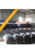 $1.25
$1.25 $1.25
$1.25 $1.25
$1.25 $1.25
$1.25 $1.25
$1.25 $1.25
$1.25 $1.25
$1.25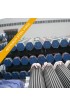 $1.25
$1.25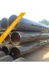 $1.25
$1.25 $1.25
$1.25 $1.25
$1.25 $1.25
$1.25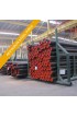 $1.25
$1.25 $1.25
$1.25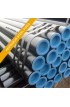 $1.25
$1.25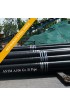 $1.75
$1.75 $2.00
$2.00 $1.00
$1.00 $1.25
$1.25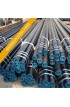 $2.40
$2.40 $4,500.00
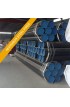 $1,000.00
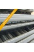 $2.00
$2.00 $1.20
$1.20 $1.25
$1.25 $1.25
$1.25 $1.25
$1.25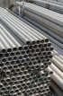 $1.25
$1.25 $1.25
$1.25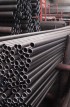 $1.25
$1.25 $0.00
$0.00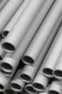 $0.00
$0.00 $1.25
$1.25 $1.25
$1.25 $1.25
$1.25 $0.00
$0.00 $1.25
$1.25 $1.25
$1.25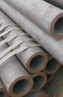 $1.25
$1.25 $1.25
$1.25 $1.25
$1.25 $1.25
$1.25 $1.25
$1.25 $1.25
$1.25 $1.25
$1.25 $1.25
$1.25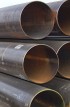 $1.25
$1.25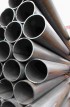 $1.25
$1.25 $1.25
$1.25 $1.25
$1.25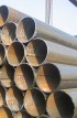 $1.25
$1.25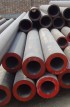 $1.25
$1.25 $1.25
$1.25 $1.25
$1.25 $1.25
$1.25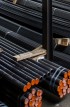 $1.25
$1.25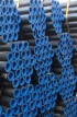 $1.25
$1.25 $1.25
$1.25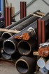 $1.25
$1.25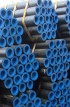 $1.25
$1.25 $1.25
$1.25 $1.25
$1.25 $0.00
$0.00


